
Technical data

Installing the ATMSpeed/155 Modules
893-01047-A 2-17
Verifying the Installation
When the ATMSpeed/155 module is installed and the cables are connected to the
ports, the module is ready for operation. All connected ports are enabled, unless
they have been disabled by SpeedView. Enabling and disabling ATMSpeed/155
module ports is described in Using SpeedView 2.1 for Windows.
You can verify the installation of an ATMSpeed/155 module by observing the
LEDs on the module while the module is operating and at system startup. This
section describes the ATMSpeed/155 module LEDs and the LED sequence at
startup.
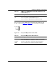
Interpreting ATMSpeed/155 Module LEDs
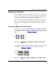
The four-port version of the ATMSpeed/155 module, the ATMSpeed/155 MCP
module, and the ATMSpeed/155 MDA and MDA MCP modules have six LEDs
for each ATM port, as shown in Figure
2-26. Table 2-1 lists the meaning of each
LED.
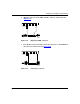
Figure 2-26. ATMSpeed/155 and ATMSpeed/155 MCP module LEDs for
ATM ports
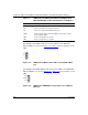
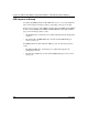
The ATMSpeed/155 MDA and MDA MCP modules have six LEDs for each ATM
port, as shown in Figure
2-27. Table 2-1 lists the meaning of each LED.
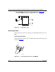
Figure 2-27. ATMSpeed/155 MDA and MDA MCP module LEDs for ATM
ports
FERF
LOF
LOS
En
RX
TX
En
RX
TX
6542
En/FERF
RX/LOF
TX/LOS
12
34
7883PEA