
Technical data


Using Local Boot (the Quick-Start Procedure)
114200-D Rev 00
B-3
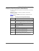
Figure B-1. ARN Module Locations
Table B-1 provides the connector names and numbers you should use during the
Quick-Start procedure.
Table B-1. Quick-Start Connector Names and Numbers
Module
Interface*
* The Quick-Start script does not support initial ISDN, X.25 PAD, or V.34 interface
configuration.
Base Expansion Adapter 1 Adapter 2
Ethernet XCVR1 XCVR2 N/A N/A
Token Ring MAU1 MAU2 N/A N/A
Serial N/A COM3, COM4,
or COM5
COM1 COM2
56/64K, FT1/T1, or
FE1/E1 DSU/CSU
N/A N/A COM1 COM2
ARN0006A
Adapter modules
Expansion module
Base module
COM3 COM4 COM5
COM
U
D
DD
B1
B2
RLSD
Run
Boot
Fail
Pwr
RPS
Fan
Base
Adapter1
Adapter2
Expansion
DCM
PCMCIA
BayStack Advanced Remote Node
RLSD3
RLSD4
RLSD5
1
2
Serial
Serial
ISDN BRI
withNT1
Tx
Rx
Cl
10BaseT
AUI
Ethernet 1