
Hardware reference guide


Palo Alto Networks Maintaining the Hardware • 19
Interpreting Status LEDs
Interpreting the Port LEDs
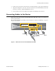
Table 5 describes the LEDs for the PA-5000 Series Ethernet ports. Refer to Figure 1.
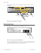
Table 6 describes the LEDs for the PA-5060/PA-5050 Gigabit Small Form-Factor Pluggable (SFP+)
ports. Refer to Figure 2.
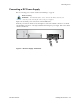
Table 7 describes the LEDs for the PA-5000 Series Management port. Refer to Figure 1 and Figure 2.
PWR 1 Green The left power supply (facing the back of the firewall) is powered and
active, or is not installed.
Red The left power supply (facing the back of the firewall) is detected but not
working.
The power supplies also have an LED that indicates the status, see
“Interpreting the Power Supply LED” on page 20.
PWR 2 Green The right power supply (facing the back of the firewall) is powered and
active, or is not installed.
Red The right power supply (facing the back of the firewall) is detected but
not working.
The power supplies also have an LED that indicates the status, see
“Interpreting the Power Supply LED” on page 20.
Table 4. Functions and States of the LED Dashboard (Continued)
LED State Description
Table 5. Ethernet and SFP Port LEDs
LED Description
Left Shows green if there is a network link.
Right Blinks green if there is network activity.
Table 6. SFP+ Port LEDs
LED Description
Left Shows green if there is a network link.
Right Blinks green if there is transmit (TX) network activity.
Table 7. PA-5000 Series Management and HA1 Port LEDs
LED Description
Left
Shows solid amber if there is a network link and blinks amber if there is
network activity.
Right
• Shows green if link is 100 Mbps
• Shows amber if link is 1 Gbps
• Shows the off state if link is 10 Mbps