PA-5000 Series Hardware Reference Guide
Contact Information http://www.paloaltonetworks.com/contact/contact/ About this Guide This guide describes the PA-5000 Series firewall hardware, provides instructions on installing the hardware, describes how to perform maintenance procedures, and provides product specifications. This guide is intended for system administrators responsible for installing and maintaining the PA-5000 Series firewall. All PA-5000 Series devices run PAN-OS, a purpose-built operating system with extensive functionality.
May 14, 2015 - Palo Alto Networks COMPANY CONFIDENTIAL Table of Contents Chapter 1 Overview . . . . . . . . . . . . . . . . . . . . . . . . . . . . . . . . . . . . . . . . . . . . . . . . . . 5 Front Panel . . . . . . . . . . . . . . . . . . . . . . . . . . . . . . . . . . . . . . . . . . . . . . . . . . 6 Back Panel . . . . . . . . . . . . . . . . . . . . . . . . . . . . . . . . . . . . . . . . . . . . . . . . . . 8 Chapter 2 Installing the Hardware . . . . . . . . . . . . . . . . . . . . . . . . .
Chapter 4 Specifications . . . . . . . . . . . . . . . . . . . . . . . . . . . . . . . . . . . . . . . . . . . . . . . 29 Physical Specifications . . . . . . . . . . . . . . . . . . . . . . . . . . . . . . . . . . . . . . . . . 29 Interface Specifications . . . . . . . . . . . . . . . . . . . . . . . . . . . . . . . . . . . . . . . . . 30 Electrical Specifications . . . . . . . . . . . . . . . . . . . . . . . . . . . . . . . . . . . . . . . . . 30 Environmental Specifications . . . . . . . . . . . . . . .
May 14, 2015 - Palo Alto Networks COMPANY CONFIDENTIAL Overview Chapter 1 This chapter describes the features of the front and back panel of the PA-5000 Series firewall.
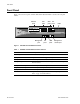
Front Panel Front Panel Figure 1 shows the front panel of the PA-5060 and PA-5050 and Table 1 describes the front panel features. Ethernet ports 1 2 3 4 5 6 7 8 9 10 SFP+ HA ports port 2 SFP ports 11 12 13 14 15 16 17 19 18 21 20 22 LEDs 23 24 PWR ALARM STS FANS HA PWR 1 TEMP PWR 2 HA2 PA-5060 MGT Management port HA1 USB HA port 1 CONSOLE USB ports Management console port Figure 1. PA-5060 and PA-5050 Front Panel Table 1.
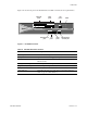
Front Panel Figure 2 shows the front panel of the PA-5020 Series and Table 2 describes the front panel features. Ethernet ports 1 2 3 4 5 6 7 8 9 10 SFP ports 11 12 13 14 15 16 17 HA port 2 LEDs 19 18 20 PWR ALARM STS FANS HA PWR 1 TEMP PWR 2 HA2 PA-5060 MGT Management port HA1 HA port 1 USB CONSOLE USB ports Management console port Figure 2. PA-5020 Front Panel Table 2.
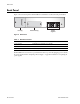
Back Panel Back Panel Figure 3 shows the back panel of the PA-5000 Series and Table 3 describes the back panel features. Fan tray Hard drive bay Power supplies Figure 3. Back Panel Table 3. Back Panel Features Item Description Power supplies 2 redundant, hot-swappable power supplies. Fan tray Removable fan tray and filter. Hard disk drive bay Hard drive bay for 2 x 2.5-inch hard disk drives. The PA-5000 Series does not have a power button.
May 14, 2015 - Palo Alto Networks COMPANY CONFIDENTIAL Installing the Hardware Chapter 2 This chapter describes how to install the PA-5000 Series firewall.
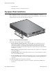
Equipment Rack Installation • Unpack the device. • Verify that power is not connected to the device. Equipment Rack Installation Before installing the hardware, read the information in “Cautions and Warnings” on page 15. Figure 4 illustrates how rack mounting brackets are attached to the PA-5000 Series. You can attach the brackets using the holes at the front or the midpoint of the unit. 21 13 9 7 5 3 1 2 4 6 17 10 16 18 23 19 22 14 8 15 11 24 20 12 Figure 4.
Connecting Cables to the Device 2. Lift the device and position it in the rack. It is recommended that two people perform this function. 3. Align the mounting holes on the side of the device with holes in the rack rail. Make sure that rack rail holes are selected so that the PA-5000 Series is level. 4. Insert mounting screws into the aligned holes. Tighten with a Phillips head screwdriver. Connecting Cables to the Device Figure 5 shows the cable connections of the PA-5060 and PA-5050.
Connecting Power Figure 6 shows the cable connections of the PA-5020. Refer to Table 2 for descriptions of the front panel interfaces. 1 3 5 7 9 11 13 15 17 19 2 4 6 8 10 12 14 16 18 20 Network SFP HA1 USB Management Console HA2 Figure 6. Cable Connections for the PA-5020 Connecting Power Figure 7 shows the AC power connections for the PA-5000 Series. Figure 7.
Connecting Power Connecting a DC Power Supply Before connecting power, read the “Cautions and Warnings” on page 15. DC Power Safety WARNING: You must shut off the electric current to the DC feed wires before connecting or disconnecting the wires to the power supplies. Figure 8 shows the DC power connections for the PA-5000 Series. Wind the power wires around the screws and tighten to secure.
Connecting Power 14 • Installing the Hardware Palo Alto Networks
May 14, 2015 - Palo Alto Networks COMPANY CONFIDENTIAL Maintaining the Hardware Chapter 3 This chapter describes how to replace power supplies, interpret LEDs, and troubleshoot hardware problems. Before continuing, read “Cautions and Warnings” on page 15.
Cautions and Warnings CAUTION: RISK OF EXPLOSION IF BATTERY IS REPLACED BY AN INCORRECT TYPE. DISPOSE OF USED BATTERIES ACCORDING TO THE INSTRUCTIONS" (Cl. 1.7.15) French Translation: ATTENTION: RISQUE D'EXPLOSION SI LA BATTERIE EST REMPLACÉE PAR UN MODÈLE DE TYPE INCORRECT. METTEZ AU REBUT LES BATTERIES USAGÉES CONFORMÉMENT AUX INSTRUCTIONS (CL. 1.7.15) CAUTION: Equipment may be affected by electrostatic discharge.
Cautions and Warnings CAUTION: All devices that use DC power are intended for installation in restricted access areas only. A restricted access area is where access can be gained only by service personnel through the use of a special tool, lock and key, or other means of security, and is controlled by the authority responsible for the location. CAUTION: For the DC input circuit, make sure there is a 15 amp circuit breaker, minimum 48VDC, and double pole on the input to the DC power.
Interpreting Status LEDs Interpreting Status LEDs This sections describes the device, port, and power supply LEDs that will enable you to determine the status of these components. • “Interpreting the Device LEDs” on page 18 • “Interpreting the Port LEDs” on page 19 • “Interpreting the Power Supply LED” on page 20 Interpreting the Device LEDs Figure 9 shows the LED dashboard on the front panel of the PA-5000 Series, and Table 4 describes the LED functions and states.
Interpreting Status LEDs Table 4. Functions and States of the LED Dashboard (Continued) LED State Description PWR 1 Green The left power supply (facing the back of the firewall) is powered and active, or is not installed. Red The left power supply (facing the back of the firewall) is detected but not working. The power supplies also have an LED that indicates the status, see “Interpreting the Power Supply LED” on page 20.
Replacing a Power Supply Interpreting the Power Supply LED The PA-5000 Series firewall has two power supplies and each power supply has an LED located above the power cord to indicate status. Table 8 describes the LEDs located on the back of each power supply. Table 8. Power Supply LED LED State Description Power Supply Green The power supply is operating normally.
Replacing a Power Supply Note: If enabled, an audible alert will be sound until two power supplies are installed and operational. The audible alert is disabled by default and can be enabled by running set system setting power-supply audiblealarm enable yes. Figure 10. AC Power Supply Replacement Replacing a DC Power Supply Before servicing the hardware, read the information in “Cautions and Warnings” on page 15.
Replacing a Hard Disk or Solid State Drive 2. Use the handle to slide the power supply out of the device, as shown in Figure 12. 3. Slide a replacement power supply into the device. 4. Wind the power wires around the screws and tighten to secure. The -48VDC connection is on the left and the 0VDC connection is on the right, as labeled when facing the power supply. 5. Turn on the electric current to the DC feed.
Replacing a Hard Disk or Solid State Drive Figure 13. Loosening the Thumbnail Screws for the Drive Bay 4. Remove the metal plate that covers the disk drive bay. 5. Push the button to the right of the drive to disengage the lever and release the drive. Figure 14. Releasing a Drive 6. Gently pull the lever open to partially eject the drive, and then slide the drive out from the enclosure. Figure 15.
Replacing a Hard Disk or Solid State Drive 7. Slide the replacement drive in, label side up, gently pushing it in until the lever begins to close. 8. Gently close the lever until it clicks into place. Figure 16. Replacing a Drive 9. Replace the metal plate and secure the thumb screws using a flat or Phillips head screw driver. 10. Power on the firewall.
Replacing the Fan Tray and Air Filter required to select which drive is primary and then given the option to reboot. Upon rebooting, the system will add the secondary drive to the primary drive’s RAID array and then the system behavior will be the same as if an identical drive was replaced. Note that it may require one extra automatic reboot to correctly set up the system (due to how automatic RAID selection works).
Replacing the Fan Tray and Air Filter 4. Remove the metal plate that covers the fan tray. 5. Hold the fan tray handle and slide the tray out. The air filter slides out along with the fan tray. Figure 18. Removing the Fan Tray and Air Filter 6. Slide the replacement fan tray in until it engages. You must slide the new tray in within 20 seconds or the firewall will power down automatically. 7. Replace the metal plate and secure the thumb screws using a flat or Phillips head screw driver.
Replacing the Fan Tray and Air Filter Replacing the Air Filter Inspect the air filter on a periodic basis. A dirty air filter restricts airflow in the unit, reducing the ventilation and effective cooling of the system. To maintain optimum system operation, Palo Alto Networks recommends that you replace the filter every 6 months. Discard used filters; do not attempt to clean and reuse them. You can purchase replacement air filters from Palo Alto Networks or an authorized reseller.
Replacing the Fan Tray and Air Filter 28 • Maintaining the Hardware Palo Alto Networks
May 14, 2015 - Palo Alto Networks COMPANY CONFIDENTIAL Specifications Chapter 4 This chapter provides specifications for the PA-5000 Series firewall. For more information, refer to the following topics: • “Physical Specifications” in the next section • “Interface Specifications” on page 30 • “Electrical Specifications” on page 30 • “Environmental Specifications” on page 31 Physical Specifications Table 9 lists physical specifications for the PA-5000 Series. Table 9.
Interface Specifications Interface Specifications Table 10 lists the interfaces for the PA-5000 Series. Table 10. Interface Specifications Specification Description Ethernet ports 12 RJ-45 10/100/1000 ports for network traffic. SFP ports Eight Small Form-Factor Pluggable (SFP) ports for network traffic. SFP+ ports PA-5060/PA-5050 only: Four 10 Gigabit Small Form-Factor Pluggable (SFP+) ports for network traffic.
Environmental Specifications Environmental Specifications Table 12 lists environmental specifications for the PA-5000 Series. Table 12.
Environmental Specifications 32 • Specifications Palo Alto Networks
May 14, 2015 - Palo Alto Networks COMPANY CONFIDENTIAL Compliance Statement Chapter 5 NEBS Requirements This section describes the Network Equipment Building System (NEBS) requirements for the PA-5000 Series. • The PA-5000 Series is intended to be installed in a Network Telecommunication Facilities (Central Office) as part of a Common Bonding Network (CNB). • The battery return (BR) input terminals are considered to be an Isolated DC return (DC-1).
VCCI Statement VCCI Statement This section provides the compliance statement for the Voluntary Control Council for Interference by Information Technology Equipment (VCCI), which governs radio frequency emissions in Japan. The following information is in accordance to VCCI Class A requirements Translation: This is a Class A product. In a domestic environment this product may cause radio interference, in which case the user may be required to take corrective actions.