
User guide
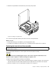


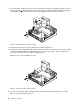

6.Pivotthetwoplasticretainingclipsthatsecuretheheatsinkfanductoutward.Thenremovetheheat
sinkfanductfromthefailingheatsinkandfanassembly.
Figure46.Removingtheheatsinkfanduct
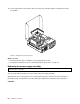
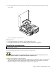
7.Placethenewheatsinkandfanassemblyonthesystemboardsothatthefourscrewsarealigned
withthecorrespondingholesinthesystemboard.Ensurethatyouproperlyplacethenewheatsink
andfanassemblysothatyoucaneasilyconnectthenewheatsinkandfanassemblycabletothe
microprocessorfanconnectoronthesystemboard.
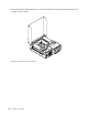
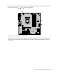
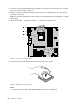
8.Followthissequencetoinstallthefourscrewstosecurethenewheatsinkandfanassembly,asshown
inFigure45“Screwsthatsecuretheheatsinkandfanassembly”onpage60:
a.Partiallytightenscrew1,thenfullytightenscrew2,andthenfullytightenscrew1.
b.Partiallytightenscrew3,thenfullytightenscrew4,andthenfullytightenscrew3.
9.Connectthenewheatsinkandfanassemblycabletothemicroprocessorfanconnectoronthesystem
board.See“Locatingpartsonthesystemboard”onpage11.
Chapter5.Installingorreplacinghardware61