Installation & Servicing Instructions Megaflo System HE A Range Gas Fired Wall Mounted Condensing Boiler These instructions include the Benchmark Commissioning Checklist and should be left with the user for safe keeping.
Natural Gas Baxi Megaflo System 15 HE A G.C.No 41 075 55 Baxi Megaflo System 18 HE A G.C.No 41 075 56 Baxi Megaflo System 24 HE A G.C.No 41 075 57 Baxi Megaflo System 28 HE A G.C.No 41 075 58 Baxi Megaflo System 32 HE A G.C.No 41 075 59 Building Regulations and the Benchmark Commissioning Checklist Building Regulations (England & Wales) require notification of the installation of a heating appliance to the relevant Local Authority Building Control Department.
Installer Notification Guidelines Choose Building Regulations Notification Route Competent Person's Self Certification Scheme Building Control Install and Commission this appliance to manufacturer's instructions Contact your relevant Local Authority Building Control (LABC) who will arrange an inspection or contact a government approved inspector Complete the Benchmark Checklist If you notify via the ‘Gas Safe Register’, the register will issue the Building Regulations certificate on members’ behalf
Legislation IMPORTANT - Installation, Commissioning, Service & Repair This appliance must be installed in accordance with the manufacturer’s instructions and the regulations in force. Read the instructions fully before installing or using the appliance. In GB, this must be carried out by a competent person as stated in the Gas Safety (Installation & Use) Regulations.
Safe Manual Handling General The following advice should be adhered to, from when first handling the boiler to the final stages of installation, and also during maintenance. Most injuries as a result of inappropriate handling and lifting are to the back, but all other parts of the body are vulnerable, particularly shoulders, arms and hands. Health & Safety is the responsibility of EVERYONE. There is no ‘safe’ limit for one man - each person has different capabilities.
CONTENTS Section 6 © Baxi Heating UK Ltd 2014 Page 1.0 Introduction 7 2.0 General Layout 8 3.0 Appliance Operation 9 4.0 Technical Data 10 5.0 Dimensions and Fixings 11 6.0 System Details 12 7.0 Site Requirements 14 8.0 Flue Options 19 9.0 Plume Displacement 24 10.0 Installation 28 11.0 Commissioning 33 12.0 Completion 36 13.0 Servicing 37 14.0 Changing Components 39 15.0 Setting the Gas Valve 46 16.0 Electrical 47 17.0 Short Parts List 48 18.
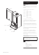
1.0 Introduction 1.1 Description 1. The Baxi Megaflo System HE A is a fully automatic gas fired wall mounted condensing system boiler. It is room sealed and fan assisted. Case Front Panel 2. The boiler is set to give a maximum output of :15 models - 15 kW 16.2 kW (Condensing) 18 models - 18 kW 19.4 kW (Condensing) 24 models - 24 kW 25.9 kW (Condensing) 28 models - 28 kW 30.3 kW (Condensing) 32 models - 32 kW 34.4 kW (Condensing) 3. It is designed for use on Natural Gas (G20). 4.
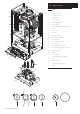
2.0 General Layout 2.1 Layout 22 1 14 21 13 12 20 15 19 6 9 8 7 11 1. Expansion Vessel 2. Automatic Air Vent 3. Circulation Pump 4. Drain Off Point 5. Pressure Relief Valve 6. Selector Switch 7. Central Heating System Pressure Gauge 8. PCB 9. Control Box 10. Gas Valve 11. Condensate Trap 12. Flame Sensing Electrode 13. Spark Electrode 14. Primary Heat Exchanger 15. Fan Assembly 16. On/Off/Reset Selector Switch 17. Central Heating Temperature Control 18.
3.0 Appliance Operation 3.1 Operating Mode (Fig. 2) Boiler Primary Circuit 1. With a demand for heating or hot water, the pump circulates water through the primary circuit. If the pressure is at least 0.5 bar the ignition sequence will start. 1 2. When the flow temperature exceeds the setting temperature, a 3 minute delay occurs before the burner relights automatically (anti-cycling). The pump continues to run during this period. 2 20 18 3 3.
4.0 Technical Data 4.1 Appliance Type C13 Appliance Category C33 C53 CAT I 2H Heat Input (Net) Max Min 15 model kW 15.4 4 18 model kW 18.5 4.3 24 model kW 24.7 7 28 model kW 28.9 9.7 32 model kW 32.8 9.7 Heat Input (Gross) Max Min 15 model kW 17.1 4.4 18 model kW 20.5 4.8 24 model kW 27.4 7.8 28 model kW 32.1 10.8 32 model kW 36.4 10.8 Heat Output (Non-Condensing) Max Min 15 model kW 15 3.9 18 model kW 18 4.2 24 model kW 24 6.
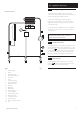
5.0 Dimensions and Fixings Dimensions At least 1.5° G A 780mm E B 345mm C 450mm D 116mm Ø Min. A E 185mm (207mm for 80/125mm flue systems) F 145mm G 131mm B H 180mm 360° Orientation H D C Tube Ø 100mm F Tap Rail 32.
6.0 System Details 6.1 Central Heating Circuit 1. The appliance is suitable for fully pumped SEALED SYSTEMS ONLY. Treatment of Water Circulating Systems 1. All recirculatory water systems will be subject to corrosion unless they are flushed and an appropriate water treatment is applied. To prevent this, follow the guidelines given in BS 7593 “Treatment of Water in Domestic Hot Water Central Heating Systems” and the treatment manufacturers instructions. 2.
6.0 System Details 6.4 System Filling and Pressurising 1. A filling point connection on the central heating return pipework must be provided to facilitate initial filling and pressurising and also any subsequent water loss replacement/refilling. Stop Valve Double Check Valve Mains Cold Water Fig. 3 Temporary Hose 2. The filling method adopted must be in accordance with all relevant water supply regulations and use approved equipment. Stop Valve 3. Your attention is drawn to: for GB: Guidance G24.
7.0 Site Requirements 450mm 5mm Min 5mm Min 7.1 200mm Min (300mm Min if using 80/125mm flueing system) Location 1. The boiler may be fitted to any suitable wall with the flue passing through an outside wall or roof and discharging to atmosphere in a position permitting satisfactory removal of combustion products and providing an adequate air supply. The boiler should be fitted within the building unless otherwise protected by a suitable enclosure i.e. garage or outhouse.
7.0 Site Requirement 7.3 Gas Service Cock Ventilation of Compartments 1. Where the appliance is installed in a cupboard or compartment, no air vents are required. 2. BS 5440: Part 2 refers to room sealed appliances installed in compartments. The appliance will run sufficiently cool without ventilation. 7.4 Gas Supply 1. The gas installation should be in accordance with the relevant standards. In GB this is BS 6891. In IE this is the current edition of I.S. 813 “Domestic Gas Installations”. 2.
Examples are shown of the following methods of termination:i) to an internal soil & vent pipe ii) via an internal discharge branch (e.g. sink waste) downstream of the trap iii) to a drain or gully iv) to a purpose made soakaway v) pumped into an internal discharge branch (e.g. sink waste) downstream of the trap vi) pumped into an external soil & vent pipe vii) to a drain or gully with extended external run & trace heating It is strongly recommended to discharge internally into the household drainage system.
v) pumped into an internal discharge branch (e.g. sink waste) downstream of the trap Sink 50mm 7.0 Site Requirement per me tre of p ipe run 2.5° M inimum fall Pipe must terminate above water level but below surrounding surface. Cut end at 45° 7.7 Condensate Drain (cont.) 12. A boiler discharge pump is available, ‘MULTIFIT’ part no. 720648301. This pump will dispose of both condensate & high temperature water from the relief valve. It has a maximum head of 5 metres.
Terminal Position with Minimum Distance (Fig. 9) (mm) A1 Directly below an opening, air brick, opening windows, etc. B1 Above an opening, air brick, opening window etc. C1 Horizontally to an opening, air brick, opening window etc. D2 Below gutters, soil pipes or drain pipes. E2 Below eaves. F2 Below balconies or car port roof. G2 From a vertical drain pipe or soil pipe. H2 From an internal or external corner. I Above ground, roof or balcony level. J From a surface or boundary line facing a terminal.
8.0 Flue Options 8.1 (ii) Horizontal Flue Systems 1. The standard flue is suitable only for horizontal termination applications. 2. All fittings should be fully engaged. The approximate engagement is 40mm. Apply soap solution to the seal on each fitting to aid assembly. (i) 3.
Vertical Flues 8.0 Flue Options 8.2 (ii) Twin & Vertical Flue Systems 1. Maximum permissible equivalent flue lengths are:(i) (60/100) 10 metres 15 metres Vertical Concentric Vertical Twin Pipe (80/125) 20 metres 2. Any additional “in line” bends in the flue system must be taken into consideration. Their equivalent lengths are:Concentric Pipes: 135° bend 0.5 metres 93° bend 1.0 metres Twin Flue Pipe 135° bend 0.25 metres For terminal position 91.5° bend 0.
8.0 Flue Options 8.
8.0 Flue Options 8.4 Air Duct Connection Twin Flue Duct Adaptor 1. The kit allows connection of a twin flue system to the boiler adaptor. Flue Duct Connection 8.5 Twin Flue Connection 1. Engage the twin flue duct adaptor in the boiler adaptor, making sure that it is pushed down as far as possible. 2. Ensure that the air & flue ducts are connected correctly and that they are adequately supported (at least once every metre using the available pipe supports). Boiler Adaptor 3.
8.0 Flue Options 8.6 1. In the case of a pitched roof 25 - 50 degrees, position the lead tile to replace/flash over existing roof tiling. Make an aperture in the roof suitable for the lower tube of the roof terminal and ensure the integrity of the roof cover is maintained. The adjustable plastic collar can either be positioned on the lead tile or the lower tube of the roof terminal prior to the final positioning of the vertical flue through the tile.
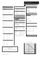
93° Elbow/Plume Outlet Assembly 9.0 Plume Displacement 9.1 60Ø Support Bracket O Ring Kit No 5118638 Content of kit 1 0.9m 60/100 Concentric Flue 1 1m 60 Dia Exhaust Flue Pipe 1 Adaptor 2 60 Dia Support Brackets 1 93° Elbow/Plume Outlet Assembly 1 Flexible Flue Trim 3 “O” Rings 1 ‘Jubilee Clip 1 Elbow 0.9 metres 60Ø Exhaust Flue Pipe 60Ø Support Bracket O Ring Fig. 13 Plume Displacement Kit (Fig. 14) Flexible Flue Trim 1.
9.0 Plume Displacement 9.2 16 14 12 60 Ø Exhaust (metres) X 60 Ø Exhaust (metres) X 14 15/1 8 10 24 8 6 4 12 8 24 8 6 28/ 32 2 0 In the graph the solid line diagonal represents the relationship between the concentric flue assembly (and any extensions) and the 60Ø exhaust (and any extensions or additional bends).
9.0 Plume Displacement 9.3 General Fitting Notes 1. Cut a hole in the external wall which the concentric flue assembly will pass through. The hole should allow the flue to fall back to the boiler at an angle of 1.5° to 3°. 2. When completed the terminal must be at least 2 metres above ground level (Fig. 19). Min. 2 metres 3. Measure and cut to size the concentric assembly and any extensions that are being used. 4. Insert the concentric assembly through the hole from outside the building. 5.
9.0 Plume Displacement Plume Outlet Elbow 9.3 General Fitting Notes (cont.) 15. For aesthetic purposes it is permissible to route the 60Ø exhaust in an enclosed box, but the air inlet and plume outlet MUST remain in free air. 16. It is also possible to separate the plume outlet from the 93° elbow to allow the flue to be installed as shown in Fig. 25. 50 0m m Mi n. 17. To do this, first slacken the two screws retaining the plume outlet to the elbow, and remove the outlet (Fig. 26).
10.0 Installation 10.1 Unpacking & Initial Preparation The gas supply, gas type and pressure must be checked for suitability before connection (see Section 7.4). NOTE: a small amount of water may drain from the boiler in the upright position. 1. Remove staples, open flaps and remove the cardboard sheet. Remove the polystyrene side pieces and literature. Two people can then lift out the boiler (Figs. 30 & 31). Fig. 30 2. After considering the site requirements (see Section 7.
10.0 Installation 10.3 Fitting The Boiler 1. Remove the sealing caps from the boiler connections. Sealing Washers NOTE: A small amount of water may drain from the boiler once the caps are removed. 2. Lift the boiler as indicated by the shaded areas. The boiler should be lifted by TWO PEOPLE. Engage the slots at the top rear of the boiler on the wall plate (Fig. 34) (see Safe Manual Handling page 5). 3. Insert the sealing washers between the valves and pipes on the wall plate and the boiler connections.
10.0 Installation 10.6 m 0m 50 Fitting The Flue HORIZONTAL TELESCOPIC FLUE m m 15 3 1. There are two telescopic sections, the Terminal Assembly and the Connection Assembly, a roll of sealing tape and two self tapping screws. A 93° elbow is also supplied. The outer duct of the Connection Assembly is painted white. On the Terminal Assembly the outer duct is unpainted. Terminal Assembly 2. The two sections can be adjusted to provide a length between 315mm and 500mm (Fig.
10.0 Installation ’ ‘Y ion ens Dim 10.6 Fitting the Flue (Cont) Securing Screw Fig. 39 ‘Peak’ to be uppermost 8. Adjust the two telescopic sections to dimension ‘Y’ (Fig. 39). Ensure that the rivets and holes in the Connection Assembly are aligned horizontally (Fig. 40). 9. Using a 2mm bit, drill through the holes at the end of the Connection Assembly into the Terminal Assembly and secure them together using the screws supplied (Fig. 39). Seal the joint with the tape provided (Fig. 41). 10.
10.0 Installation 10.7 Making The Electrical Connections The boiler is fitted with a 1.3m length of 3 core of cable. This can be connected to the fused 3A 230V 50HZ supply. NOTE: Both the Live and Neutral connections are fused. To connect an external control proceed as follows:1. Slacken the facia panel securing screws and lift the outercase panel so that its securing tabs are clear of the facia. Remove the panel. Cable Clamp Fig. 46 2.
11.0 Commissioning 11.1 Commissioning the Boiler 1. Reference should be made to BS:EN 12828 & 14336 when commissioning the boiler. 2. At the time of commissioning, complete all relevant sections of the Benchmark Checklist at the rear of this publications. Screw 3. Ensure that the filling loop is connected and open, then open the heating flow and return valves on the boiler. 4. Open the screw on the automatic air vent on the pump body (Fig. 49).
Set Boiler to Maximum Rate (see 11.1.11) Allow the combustion to stabilise. Do not insert probe to avoid ‘flooding’ the analyser. Verify Flue Integrity Indication that products of combustion & inlet air are mixing - further investigation is required. Check all flue components are correctly assembled, fixed & supported. Check the flue & terminal are unobstructed. Is O2 ≥ 20.6% and CO2 < 0.2% ? No TURN APPLIANCE OFF ! Call 0844 871 1555 for advice.
11.0 Commissioning x2 11.3 Check the Operational (Working) Gas Inlet Pressure 1. Ensure that all controls are calling for heat, and the selector switch is in the central heating and hot water position ( ). The current boiler temperature is shown on the display. Central Heating Temperature Control Selector Switch 2. To check the gas rate it is necessary to set the boiler to ‘Calibration Mode’. Calibration Control Fig. 52 3.
12.0 Completion 12.1 Case Front Panel Completion 1. Instruct the user in the operation of the boiler and system including external controls, explaining the operational sequence. 2. Set the central heating and hot water temperature control knobs to the requirements of the user. 3. Carefully read and complete all sections of the Benchmark Commissioning Checklist at the rear of this publication that are relevant to the appliance and installation.
13.0 Servicing 13 .1 Annual Servicing 1. For reasons of safety and economy, it is recommended that the boiler is serviced annually. Servicing must be performed by a competent person in accordance with B.S. 7967-4. Case Front Panel 2. After servicing, complete the relevant Service Interval Record section of the Benchmark Commissioning Checklist at the rear of this publication.
4 ±0.5 Burner 13.0 Servicing 13.2 Viewing Window Annual Servicing - Inspection (Cont) 6. Undo the nut on the gas inlet pipe to the venturi (Fig. 63) and pull the sensing pipe off the fan. 7. Disconnect the electrode leads, noting their position, and the fan electrical plugs (Fig. 62). Sensing Electrode 7.5 ±1 Spark Ignition Electrode 10 ±1 8. Undo the four nuts retaining the combustion box cover to the heat exchanger. 9.
14.0 Changing Components Bracket Igniter Igniter Feed Plug IMPORTANT: When changing components ensure that both the gas and electrical supplies to the boiler are isolated before any work is started. When the component has been changed turn the selector switch fully anticlockwise against the spring pressure to the reset position and hold for 5 seconds to reset the boiler before recommissioning. See Section 13.2 “Annual Servicing” for removal of case panel, door etc. 14.1 Electrode Leads Igniter (Fig.
14.0 Changing Components 14.3 Fan (Fig. 66) 1. Undo the nut on the gas inlet pipe to the venturi (Fig. 67) and pull the sensing pipe off the fan. 2. Disconnect the electrode leads, noting their position and disconnect the fan electrical plugs. 3. Undo the screws securing the collector to the extension piece. 4. Remove the collector and fan assembly, being careful to retain the injector in the venturi. 5. Undo the screws securing the fan to the venturi and fit the new fan.
14.0 Changing Components Cover 14.6 Burner Burner (Fig. 69) 1. Undo the screws securing the collector to the venturi and extension piece. Remove this extension piece from the cover (on 24 models). Gasket Extension Piece (Not on 28 model) 2. Withdraw the burner from the cover and replace with the new one. Gasket 3. Examine the gasket, replacing if necessary. 4. Reassemble in reverse order. Venturi 14.7 Insulation (Fig. 70) 1. Remove the electrode leads, noting their positions.
14.0 Changing Components Electrical Plug 14.8 Flue/Heat Exchanger Thermostat Sensor Flue/Heat Exchanger Thermostat Sensor (Fig. 71) 1. Ease the retaining tab on the sensor away and disconnect the electrical plug. 2. Turn the sensor 90o anticlockwise to remove - it is a bayonet connection. 3. Reassemble in reverse order. 14.9 Fig. 71 Water Pressure Sensor (Fig. 73) 1. Drain the primary circuit. 2. Disconnect the two wires from the sensor. 3.
14.0 Changing Components 14.13 Pump - Head Only (Fig. 75) 1. Drain the primary circuit and remove the socket head screws securing the pump head to the body and draw the head away. 2. Undo the screw on the pump wiring cover and remove the cover. Using a suitable flat bladed screw driver press the cable securing levers downwards to release each wire after noting their position. 3. A standard replacement Grundfos 15-60 head can now be fitted. Connect the pump wiring to the new head.
Gauge Retaining Bracket 14.0 Changing Components 14.16 Pressure Gauge (Figs. 78 & 79) 1. Drain the primary circuit and undo the nut on the pressure gauge capillary. Pressure Gauge 2. Undo the screws securing the gauge retaining bracket. Fig. 78 3. Remove the bracket and gauge assembly. Depress the barbs on the side of the gauge and remove the retaining bracket. 4. Examine the sealing washer, replace if necessary. 5. Reassemble in reverse order. Fig. 79 14.
14.0 Changing Components Venturi Inlet Pipe 14.23 Gas Valve (Fig. 83) IMPORTANT: After replacing the valve the CO2 must be checked and adjusted as detailed in Section 15.0 Setting the Gas Valve. Only change the valve if a suitable calibrated combustion analyser is available, operated by a competent person - see section 13.1. Gas Valve Sensing Pipe 1. Turn the gas cock off and undo the nut on the gas feed elbow under the boiler. Power Lead 2.
x2 15.0 Setting the Gas Valve 15.1 Central Heating Temperature Control Selector Switch IMPORTANT: The CO2 must be only be checked and adjusted to set the valve if a suitable calibrated combustion analyser is available, operated by a competent person - see Section 13.1 Calibration Control Fig. 86 1. The combustion (CO2) may be checked after running the boiler for several minutes. To do this it is necessary to set the boiler to ‘Calibration Mode’. Display 2.
16.0 Electrical 16.
17.0 Short Parts List Short Parts List Key No. G.C. No. Description Manufacturers Part No.
18.0 Fault Finding 18.1 NOTE: When instructed to turn the selector to the reset position turn the selector switch fully anticlockwise against the spring pressure to the reset position and hold for 5 seconds to reset the boiler. Initial Fault Finding Checks 1. Check that gas, water and electrical supplies are available at the boiler. 2. Electrical supply = 230V ~ 50 Hz. 3. CH water system pressurised to 0.5 bar minimum when the boiler is cold. 4. The preferred minimum gas pressure is 20 mbar. 5.
18.0 Fault Finding Refer to Section 16.0 “Illustrated Wiring Diagram” for position of terminals and components Central Heating - Follow operational sequence Turn selector switch to The display illuminates NO Go to section ‘A’ YES Error 110 flashing Error 130 flashing Error 133 flashing YES Turn the selector switch to reset position for 5 seconds YES If the error 110 is still flashing.
18.0 Fault Finding Fault Finding Solutions Sections A Is there 230V at: 1. Main terminals L and N 2. Main terminal fuse 3. B NO Check electrical supply NO Replace fuse NO Check wiring PCB - X1 connector terminals 1,2 NO Display illuminated Replace PCB Is there 230V at: YES 1. Pump 2. PCB - X3 connector terminals 3 & 4 NO If pump jammed, release NO Replace pump Replace PCB YES Change pump supply cable C 1. YES CH system pressure less than 0.5 bar NO 2. D 1.
18.0 Fault Finding E F Temperature sensors faulty. Cold resistance approximately 10kΩ @ 25° C (DHW and CH sensors) 20kΩ @ 25° C (Flue sensor) (resistance reduces with increase in temp.) 1. 2. NO Replace sensor Check and correct the connection of the tube between the venturi and gas valve Gas at burner NO Ensure gas is on and purged PCB - X3 connector is 230V AC across terminals 1 & 2 YES Replace gas valve NO Replace PCB Check and correct if necessary 1. Ignition electrode and lead 2.
18.0 Fault Finding H 1. 2. Check supply pressure at the gas valve:Minimum 17mbar Check and correct if necessary 1. The mechanical set of the gas valve (CO2 values - see instruction) 2. Flame sensing electrode and lead connections 3. Flame sensing electrode position YES Flame current should be more than 0.5 μ A I 1. Overheat thermostat operated or faulty, i.e. continuity across thermostat terminals NO NO Replace PCB Replace flame sensing electrode Allow to cool.
GAS BOILER SYSTEM COMMISSIONING CHECKLIST This Commissioning Checklist is to be completed in full by the competent person who commissioned the boiler as a means of demonstrating compliance with the appropriate Building Regulations and then handed to the customer to keep for future reference. Failure to install and commission according to the manufacturer’s instructions and complete this Benchmark Commissioning Checklist will invalidate the warranty. This does not affect the customer’s statutory rights.
SERVICE RECORD It is recommended that your heating system is serviced regularly and that the appropriate Service Interval Record is completed. Service Provider Before completing the appropriate Service Record below, please ensure you have carried out the service as described in the manufacturer’s instructions. SERVICE 01 Date: SERVICE 02 Engineer name: Engineer name: Company name: Company name: Telephone No: Telephone No: Gas safe register No: Record: At max.
All descriptions and illustrations provided in this leaflet have been carefully prepared but we reserve the right to make changes and improvements in our products which may affect the accuracy of the information contained in this leaflet. All goods are sold subject to our standard Conditions of Sale which are available on request. BAXI A Tr a d in g D i v i s i o n o f B ax i H eat i ng U K Lt d ( 3879156) Brooks House, Coventry Road, Warwick.