
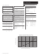
Technical data
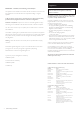

9
3.0 Appliance Operation
© Baxi Heating UK Ltd 2012
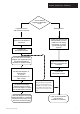
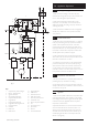
3.1 Operating Mode (Fig. 3)
1. With a demand for heating or hot water, the pump
circulates water through the primary circuit. If the flow is 4.0
L/min or above the ignition sequence will start.
2. When the flow temperature reaches the set point
temperature, a 5 minute delay occurs before the burner
relights automatically (anti-cycling). The pump continues to
run during this period.
3. When the demand is satisfied the burner is extinguished
and the pump continues to run for a period of 5 minute
(Pump Overrun).
3.2 Frost Protection Mode
1. If the boiler return temperature falls below 7° C, then the
boiler pump and heating circuit pump/valve are activated or
opened. If the temperature rises above 8° C, the frost
protection function will be terminated. If the boiler return
temperature falls below 3°C, the supplementary burner will
be switched on until the return temperature reaches 25°C
and the appliance frost protection is stopped.
2. If the supplementary burner is locked, the engine burner
will be used. In this case, the return temperature limit to start
the burner is increased from 3 to 10°C.
3. If an existing room thermostat is to be used then further
protection for the system can be incorporated by using a
wall mounted frost thermostat. In certain circumstances it
may be necessary to fit a pipe thermostat. If the THINK
Controller is used as a room sensor then it will act as a room
frost protection unit as well - see Section 10.15.
3.3 Pump/Diverter Valve Protection
1. The pump and valve kick is a protective function aimed at
preventing the pumps and valves from seizing.
2. Every friday at 3.00am, the pumps and valves connected
directly to the boiler unit are switched on 30 seconds and off
for 30 seconds, one by one.
3.4 Legionella
1. When a DHW cylinder is fitted with a temperature sensor
an anti-legionella function can be activated, so that at initial
DHW charge and there after at regular intervals the cylinder
is heated to destroy any legionella bacteria, the cylinder
temperature is raised to 65°C.
2. By default this function is not active. Customers have the
choice to activate the function and set how often, or on
what day, and at what time this function runs. Customers
should be informed that the temperature reached may be
considerably higher than their normal requirements (See
Section 11.3 paragraph j).
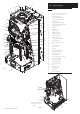
Key
1 Supplementary Heat Exchanger
2 Burner - Supplementary
3 Ignition Electrodes
4 Flame Sensing Electrodes
5 Supplementary Gas Valve
6 Engine Burner
7 Engine Ignition Electrode
8 Engine Flame Sensing Electrode
9 Engine Gas Valve
10 Gas Inlet
11 Boiler Flow
12 Boiler Return
1
2
3
4
5
6
7
8
9
10
11
12
13
14
15
16
24
19
18
20
21
22
23
23
16
17
13 Engine Alternator
14 PCB Control
15 Water Flow Sensor
16 Safety Thermostats
17 Flow Temperature Sensor
18 Condensate Trap
19 Return Temperature Sensor
20 Fan
21 Spool Valve Motor
22 Spool Valve
23 Venturis
24 Overtravel Switches
Fig. 3