
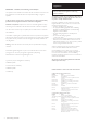
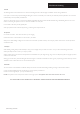
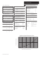
Technical data

8
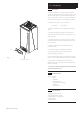
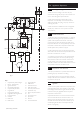
2.0 General Layout
© Baxi Heating UK Ltd 2012
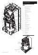
2.1 Layout
1 Supplementary Heat Exchanger
2 Burner - Supplementary
3 Ignition Electrodes
4 Flame Sensing Electrodes
5 Supplementary Gas Valve
6 Engine Burner
7 Engine Ignition Electrode
8 Engine Flame Sensing Electrode
9 Engine Gas Valve
10 Gas Inlet
11 Boiler Flow
12 Boiler Return
13 Engine Alternator
14 PCB Control/Cover
15 Water Flow Sensor
16 Safety Thermostats
17 Flow Temperature Sensor
18 Condensate Trap
19 Return Temperature Sensor
20 Fan
21 Spool Valve Motor
22 Spool Valve
23 Venturis
24 Overtravel Switches x 2
25 Combustion Test Point
26 Air Feed Test Point
27 Transit Bracket
28 Engine Head Thermocouples
29 Service Reset Button
30 Overcurrent Switch
31 Start/Stop Resistors
32 THINK Controller
33 Drain
34 Ignition Coils
35 Ambient Sensor
36 Wall Plate
37 EMC Mains Filter
Fig. 2
1
2
3
4
5
6
7
8
9
10
11
12
13
14
33
16
17
18
19
20
21
22
23
24
25
26
27
28
View from Underneath
Bottom cover removed
for Clarity
Fig. 2a
32
7
8
29
30
10
31
18
15
34
34
35
36
37