
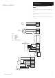
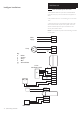
Technical data
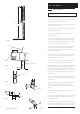

33
9.0 Installation
© Baxi Heating UK Ltd 2010
NOTE: - Installers of this appliance must have undergone
Baxi Ecogen Training and been approved to install this
appliance.
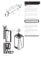
9.1 Unpacking & Initial Preparation
NOTE: Maintain the appliance upright at all times. Do not
lay the appliance on its back, sides or front. Drilling of the
wall or ceiling for flue and pipe work must be completed
before the appliance is fitted to the wall.
The gas supply, gas type and pressure must be checked for
suitability before connection (see Section 7.5).
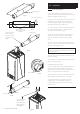
a) Remove the shrink wrap and literature pack.
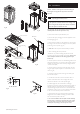
b) Remove the upper packaging to leave the appliance on the
base packaging (Fig. 23).
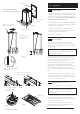
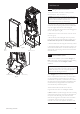
c) Remove the back plate from the appliance by removing the
2 securing screws and undo the 2 fixing nuts on the top of the
panel using a 10mm spanner (Fig. 24).
d) Take care:- The back panel can fall suddenly on release.
1. After considering the site requirements
(see Section 7.0) position the fixing template on the wall
ensuring it is level both horizontally and vertically. Ensure that
there is adequate clearance for the lifting equipment (see
Section 7.2).
2. Mark the position of the six most suitable fixing holes for the
wall plate positions B+C (as marked on the template). Where
possible mark the position of the centre top fixing position A
(marked on template).
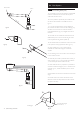
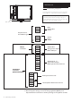
3. Mark the position of the centre of the flue hole (rear exit)
using the paper template supplied. For side flue exit, mark as
shown (Fig. 25).
4. If required, mark the position of the gas and water pipes.
Remove the template.
5. Cut the hole for the flue (minimum diameter 116mm, a
minimum horizontal hole of 116mm will give the correct
clearance for the flue to run at the required angle).
6. Drill the single hole (10mm diameter for wall plugs
provided) as previously marked and position the back plate on
the wall position A on template. Push one of the wall plugs
supplied through the plate and secure it to the wall with one
of the 80mm screws (Fig. 26). If is not possible to use Position
A use one of the other six positions marked B+C.
7. Check that the top edge is horizontal with a spirit level.
Retighten the screw. Drill the remaining 6 positions at B+C
and secure the back plate to the wall.
8. For correct installation the back plate must be absolutely
flat and vertical - check before mounting the boiler. If there
is any unevenness or the back plate is not mounted in the
vertical plane use packing to correct any out of true.
133mm
For Side Flue Exit
Fig. 25
Remove Screws
Loosen Securing
Nuts
Hinge up the Securing
Nuts to remove Back Plate
Back Plate
Fig. 22
Fig. 23
Fig. 24
Fig. 26