
Technical data

12.0 Commissioning the Boiler
37
© Baxi Heating UK Ltd 2007
12.1 Commissioning the Boiler
1. Reference should be made to BS 5449 Section 5 when
commissioning the boiler.
2. Flush the whole system using a suitable flushing agent
(see Section 6.2) and vent the radiators. Check for water
leaks.
3. Refill the system with inhibitor following the inhibitor
manufacturer’s instructions and BS 7593 Code of Practice
for Treatment of Water in Domestic Hot Water Central
Heating Systems (see Section 6.2).
4. Complete the label supplied with the inhibitor and
attach to the inside of the boiler case. Detail of system
treatment should be added for future reference.
5. Turn the gas supply on and purge according to in GB
BS 6891 and in IE I.S. 813 “Domestic Gas Installations”.
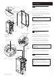
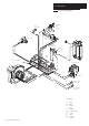
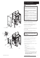
6. Remove the top RH securing screw and hinge down
the PCB housing to gain access to the gas service cock
(see Fig. 32). Turn the gas service cock anticlockwise to
the ON position and check for gas soundness up to the
gas valve (Fig. 34).
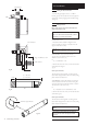
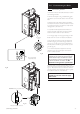
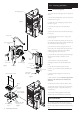
7. Turn the flow temperature adjustment screw fully
clockwise (Fig. 35) and run the system and check the
boiler for correct operation.
NOTE: The 12,15, 18, 24 models are self-regulating
dependent upon the system load. The 30 model will
modulate between inputs of 33.76kW and 10.3kW.
The 30 model input is factory set at 24.5kW and can
be altered to 33.76kW - see section 10.8. No
adjustment of the gas valve is permissible.
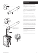
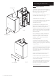
8. With the system cold and all controls calling for heat
check the gas pressure at the inlet tapping of the gas valve
(Fig. 36). The pressure must be a minimum of 18.1 mbar
(Working Pressure). Check that the gas rate is no greater
than quoted in Section 4.0, ‘Technical Data’.
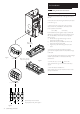
WARNING: The PCB Control and Fan
Assembly are 325 Vdc. Isolate at supply
before access.
Low
High
Reset
ON
IN OUT
Gas Service
Cock
Flow Temperature
Adjustment Screw
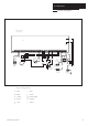
Fig. 34
Fig. 35
Fig. 36
Open
Inlet Gas Pressure Test Point
DO NOT check gas pressure here