Installation & Service Instructions Promax SL Range These instructions include the Benchmark Commissioning Checklist and should be left with the user for safe keeping.
Natural Gas Building Regulations and the Benchmark Commissioning Checklist Potterton Promax 12 SL G.C.No 41 591 79 Potterton Promax 15 SL G.C.No 41 591 87 Potterton Promax 18 SL G.C.No 41 591 80 Potterton Promax 24 SL G.C.No 41 591 88 Potterton Promax 30 SL G.C.No 41 591 89 Building Regulations (England & Wales) require notification of the installation of a heating appliance to the relevant Local Authority Building Control Department.
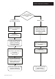
Installer Notification Guidelines Choose Building Regulations Notification Route Competent Person's Self Certification Scheme Building Control Install and Commission this appliance to manufacturer's instructions Contact your relevant Local Authority Building Control (LABC) who will arrange an inspection or contact a government approved inspector Complete the Benchmark Checklist If you notify via CORGI Scheme, CORGI will then notify the relevant Local Authority Building Control Scheme on member's beha
Legislation IMPORTANT - Installation, Commissioning, Service & Repair This appliance must be installed in accordance with the manufacturer’s instructions and the regulations in force. Read the instructions fully before installing or using the appliance. In GB, this must be carried out by a competent person as stated in the Gas Safety (Installation & Use) Regulations.
Safe Manual Handling General The following advice should be adhered to, from when first handling the boiler to the final stages of installation, and also during maintenance. Most injuries as a result of inappropriate handling and lifting are to the back, but all other parts of the body are vulnerable, particularly shoulders, arms and hands. Health & Safety is the responsibility of EVERYONE. There is no ‘safe’ limit for one man - each person has different capabilities.
Contents Section 1.0 Introduction 7 2.0 General Layout 8 3.0 Appliance Operation 9 4.0 Technical Data 10 5.0 Dimensions and Fixings 11 6.0 System Details 12 7.0 Site Requirements 16 8.0 Flue Options 20 9.0 Plume Displacement 25 10.0 Installation 29 11.0 Electrical 35 12.0 Commissioning the Boiler 37 13.0 Fitting the Outer Case 38 14.0 Servicing the Boiler 39 15.0 Changing Components 41 16.0 Short Parts List 48 17.
1.0 Introduction 1.1 Description 1. The Potterton Promax SL range are gas fired room sealed fan assisted condensing central heating boilers. 2. The maximum output of the Potterton Promax 12 SL is 40,330 Btu/hr,15 SL model is 52,000 Btu/hr, 18 SL model is 60,770 Btu/hr and 24 SL model is 75,000 Btu/hr. The maximum output of the 30 SL model is preset at 75,000 Btu/hr but can be set to 100,000 Btu/hr (see section 10.8). All boilers automatically adjust their outputs according to the system load. 3.
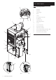
2.0 General Layout 2.1 16 Fig. 5 15 14 2 1 3 13 12 4 5 6 Fig. 3 7 9 8 11 Fig. 4 8 © Baxi Heating UK Ltd 2007 Fig. 6 10 Layout (Figs. 3,4,5 & 6) 1. Wall Plate 2. Flue Elbow 3. Heat Exchanger 4. Burner 5. Air Box 6. Fan Protection Thermostat 7. Fan Assembly 8. Condensate Trap 9. PCB Housing Assembly 10. Gas Tap 11. Gas / Air Ratio Valve 12. Flow Pipe Connection 13. Return Pipe Connection 14. Flow Temperature Safety Thermostat - Black 15.
Mains On. 3.0 Appliance Operation 3.1 Flow temperature less than set point ? NO 1. Switched Live On: When the switched live switches on if the flow temperature is less than the set point then pump overrun occurs. When the switched live switches on if the flow temperature is greater than the set point then pump overrun occurs. YES 10 second Pump On. 2. Pump On: The pump is on while the fan, spark generator and gas valve are off. After 10 seconds if the flow switch has made then fan pre-purge occurs.
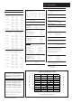
4.0 Technical Data Appliance Type C13 C33 Appliance Category C53 Max Gas Rate (After 10 Mins) CAT I 2H (12) (2H - G20 - 20mbar) (15) (18) (30) Btu/hr 40,950 52,000 61,400 75,000 102,980 m3/hr 1.34 1.64 1.94 2.31 2.95 ft3/hr 47.3 52.1 68.5 83.3 104.2 Heat Input (Q)(Gross) Max Min 12 model kW Btu/hr 13.34 45,518 10.2 34,840 15 model kW Btu/hr 16.88 57,600 10.2 34,840 Injector (Natural Gas) 6.5mm Diameter 18 model kW Btu/hr 20.18 68,850 10.
5.0 Dimensions and Fixings DIMENSIONS A 600mm E 1.5° B 280mm C 390mm A D 150mm Ø Min. E 162.5mm F 96mm B 360° Orientation C D Tube Ø 110mm The 1.5° fall provided by the elbow is to allow condensate to run back to the boiler, for disposal through the condensate discharge pipe. Fig. 7 F Y X 1.5° SIDE FLUE (left and right) For every 1m of horizontal flue length, the clearance above the top of the flue elbow should be 27.5mm to incorporate the 1.5° fall in the flue from the terminal to the elbow.
6.0 System Details 6.1 Water Circulating Systems 1. The appliance is suitable for use with open vent fully pumped systems and sealed systems . The following conditions should be observed on all systems: • The static head must not exceed 30m (100ft) of water. • The boiler must not be used with a direct cylinder. • Drain cocks should be fitted to all system low points. • All gas and water pipes and electrical wiring must be installed in a way which would not restrict the servicing of the boiler.
6.0 System Details Copper 0.5m Copper 0.5m Flow Boiler 6.3 Return Copper 1m 1. The sizes of flow and return pipes from the boiler should be determined by normal methods, according to the requirements of the system. The connections on the boiler are 22mm. Fig. 9 mm 500 45° 1000mm Min Pipework 2. A 20 °C (36°F) drop in temperature across the system is recommended for condensing boilers.
230V 50Hz Key to colours L N E Y Plan Diverter Valve b g/y w Cylinder Stat gr 1 Room Stat o C 2 Boiler L E N P/F Timer L N CH on HW on HW off Y Plan, Room Thermostat System, CH Interlocked By Room Thermostat At least the Radiator(s) near the Room Thermostat not TRV’d Pump run from Switched Live By-pass permitted but not required for Part L1 compliance gr 230V 50Hz b gr L N E Motor b br Blue Brown White Orange Grey Green/Yellow 6.0 System Details 6.
6.0 System Details 3 Litre Top Up Bottle (if required) Air Vent Safety Valve Filling Point Pressure Gauge Pump Radiator Circuit Expansion Vessel System Drains at Low Point Max Boiler Flow Temp = 82° C Method of determining minimum valve of expansion vessel volume for sealed systems using Potterton Boilers Vessel Charge Pressure (Bar) Initial System Pressure (Bar) Multiply Total Water Content Of System By (Litres) 0.5 0.5 1.0 1.5 2.0 0.067 0.112 0.207 0.441 1.0 1.5 2.0 0.087 0.152 0.330 1.
7.0 Site Requirements 7.1 Location NOTE: Due to the high efficiency of the boiler a plume of water vapour will be discharged from the flue. This should be taken into account when siting the flue terminal. 1. The boiler may be fitted to any suitable wall with the flue passing through an outside wall or roof and discharging to atmosphere in a position permitting satisfactory removal of combustion products and providing an adequate air supply.
390mm 5mm Min 5mm Min 7.0 Site Requirements 7.3 Clearances (Figs. 15 &16) 200mm 1. A flat vertical area is required for the installation of the boiler. 2. These dimensions include the necessary clearances around the boiler for case removal, spanner access and air movement. Additional clearances may be required for the passage of pipes around local obstructions such as joists running parallel to the front face of the boiler. 600mm 3. For unventilated compartments see Section 7.2. 7.4 Gas Supply 1.
Termination to an internal soil and vent pipe 7.0 Site Requirements 7.6 Boiler Condensate Drain FAILURE TO INSTALL THE CONDENSATE DISCHARGE PIPEWORK CORRECTLY WILL AFFECT THE RELIABLE OPERATION OF THE BOILER 50mm per me 2.5° M inimum tre of pipe ru The condensate discharge pipe MUST NOT RISE at any point along its length. There MUST be a fall of AT LEAST 2.5° (50mm per metre) along the entire run. n fall NOTE: It is unnecessary to fit an air break in the discharge pipe.
Terminal Position with Minimum Distance (Fig. 17) (mm) Aa Directly below an opening, air brick, opening windows, etc. 300 Ba Above an opening, air brick, opening window etc. 300 Ca Horizontally to an opening, air brick, opening window etc. 300 D Below gutters, soil pipes or drain pipes. 25 E Below eaves. 25 F Below balconies or car port roof. 25 G From a vertical drain pipe or soil pipe. 25 (i) 25 (ii) 115 H From an internal (i) or external (ii) corner. I Above ground, roof or balcony level.
8.0 Flue Options 8.1 Y X Horizontal Flue Systems Concentric The maximum equivalent lengths are 4m (horizontal) or (vertical). Their lengths exclude the standard elbow and flue/terminal assembly (horizontal) and terminal assembly (vertical). Any additional “in line” bends in the flue system must be taken into consideration. Their equivalent lengths are: Horizontal Flue System Examples X Plume Displacement 70/110 dia Kit 1M Extensions, 45° & 93° bends are also available - see Section 9.
Vertical Flue System Examples (Twin Pipe) 8.0 Flue Options 8.2 Twin & Vertical Flue Systems Concentric The maximum equivalent lengths are 4m (vertical). Their lengths exclude the standard elbow and terminal assembly (vertical). Y Twin Flue The total maximum equivalent flue length is 150m. NOTE: Each 1m of flue duct should be calculated as 2m. X Any additional “in line” bends in the flue system must be taken into consideration.
8.0 Flue Options 8.
8.0 Flue Options For Vertical Flues 8.4 Vertical Flue Adaptor For Vertical Flue Systems 1. Undo the screws securing the blanking plate to the boiler top panel. Discard the plate. Gasket 2. Fix the vertical adaptor and gasket to the top panel with the previously removed screws. 8.5 For Twin Flue Systems 1. Undo the screws securing the blanking plate to the boiler top panel. Discard the plate. 2. Fix both the air and flue adaptors with their gaskets onto the boiler top panel. Secure with screws.
8.0 Flue Options 8.6 1. In the case of a pitched roof 25 - 50 degrees, position the lead tile to replace/flash over existing roof tiling. Make an aperture in the roof suitable for the lower tube of the roof terminal and ensure the integrity of the roof cover is maintained. The adjustable plastic collar can either be positioned on the lead tile or the lower tube of the roof terminal prior to the final positioning of the vertical flue through the tile.
9.0 Plume Displacement Plume Outlet (‘Peak’ MUST be Uppermost) 9.1 Plume Displacement Kit (P.D.K.) Kit No 5121371 Content of kit 1 70/110 Concentric Flue 1 1m 70 Dia Exhaust Flue Pipe 2 Support Brackets 1 93° Elbow/Plume Outlet Assembly 1 Flue Trim 2 “O” Rings 1 Elbow with Gasket 0.94 metre 1. This kit is recommended for installations where the condensate plume emitted from the flue may cause a nuisance or affect the surroundings. 2.
30 30 28 28 26 26 18 4 &2 30 70Ø Exhaust (metres) 18 70Ø Exhaust (metres) 15, 20 4 &2 30 16 22 18 18 24 15, 20 12, 12, 24 22 9.0 Plume Displacement 14 12 10 16 9.2 In the graph the solid line diagonal represents the relationship between the concentric flue assembly (and any extensions) and the 70Ø exhaust (and any extensions or additional bends). 14 12 10 8 8 6 6 4 4 2 2 0 Example 1 - Not Permissible If, for instance, a concentric length of 3.
9.0 Plume Displacement 9.3 This section of the flue MUST be horizontal Min. 2 metres General Fitting Notes - P.D.K. 1. Cut a hole in the external wall which the horizontal concentric flue assembly will pass through. 2. When completed the terminal must be at least 2 metres above ground level (Fig. E). 3. Measure and cut to size the concentric assembly and any extensions that are being used. 4.
9.0 Plume Displacement Plume Outlet Elbow 9.3 General Fitting Notes - P.D.K. (cont.) 16. For aesthetic purposes it is permissible to route the 70Ø exhaust in an enclosed box, but the air inlet and plume outlet MUST remain in free air. 500 mm Min . Fig. H 200mm Min. Fig. I 200mm Min. Fig. J 28 © Baxi Heating UK Ltd 2007 17. It is also possible to separate the plume outlet from the 93° elbow to allow the flue to be installed as shown in Fig. H. 18.
Template Literature Pack 10.0 Installation Wall Plate Check Site Requirements (section 7) before commencing. 10.1 Initial Preparation The gas supply, gas type and pressure must be checked for suitability before connection (see Section 7.4). Fig. 19a 1. Cut the banding and remove the fixing template, wall plate and literature pack (Fig. 19a) from the carton.
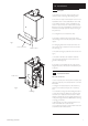
10.0 Installation 10.2 Preparing The Boiler 1. Remove the outer carton and packaging. 2. Lift the outercase upwards and remove. 3. Remove the internal packaging. Fig. 22a Internal Polysterene Packaging Piece Lower Door Panel Outercase Break Off Upper & Lower Pipe Run Options Fig.
10.0 Installation 10.3 Retaining Bracket Fitting The Boiler (Fig. 24) 1. Obtain retaining bracket and two M6 nuts from fitting bag. 2. Offer up the boiler to the wall plate using the lifting points shown in Fig. 24 and locate the rear bottom edge onto the self locating support at the base of the wall plate. (See Safe Manual Handling page 5.) NOTE: When installing in a Loft/Small Compartment, access for lifting the boiler from the front can be gained for two people using the lifting points. (Fig. 24).
10.0 Installation Wall Thickness 10.6 Making the Gas Connection 1. Connect the gas supply to the G1/2 (1/2in BSPT Internal) gas tap. This is located on the lower right side of the boiler, access by hinging down the PCB housing (see Fig. 32). 1.5° 10.7 Fitting The Flue Before fitting the flue, check the condensate drain integrity (see section 10.5). IMPORTANT: The flue should always be installed with a 1.5° fall from terminal to elbow, to allow condensate to run back to the boiler. HORIZONTAL FLUE 1.
10.0 Installation 10.7 Inner Flue Support Bracket Fitting the Flue (Cont) 6. Ensure the inner flue support bracket is positioned in the flue (Fig. 28). 7. Engage the flue into the flue elbow using soap solution to ease the engagement ensuring the flue is assembled as shown (Fig. 29). Take the tape supplied in the kit and wrap around the joint between the flue and the elbow (Fig. 29a). Fig. 28 8. Place the gasket over the flue exit on the boiler. Flue 9.
10.0 Installation 10.8 Making The Electrical Connections WARNING: This appliance must be earthed 1. The electrical connections are on the right hand side of the unit. 2. Undo the two screws securing the cable clamp and place to one side (Fig. 31). 3. The Promax 30 SL is factory set to give a maximum output of 22.0 kW (75,000 Btu/hr).
11.0 Electrical 11.
11.0 Electrical 11.
12.0 12.1 Commissioning the Boiler Commissioning the Boiler 1. Reference should be made to BS 5449 Section 5 when commissioning the boiler. 2. Flush the whole system using a suitable flushing agent (see Section 6.2) and vent the radiators. Check for water leaks. 3. Refill the system with inhibitor following the inhibitor manufacturer’s instructions and BS 7593 Code of Practice for Treatment of Water in Domestic Hot Water Central Heating Systems (see Section 6.2). 4.
13.0 13.1 Fitting the Outer Case Fitting The Outer Case Break Off Panel 1. Position the outercase over the boiler engaging the lugs in the side flanges over the hooks on the wall plate. Break off top or bottom panel as required to accommodate pipework runs (Fig.37). 2. Using the two screws supplied in the kit, secure the outercase to the combustion box (Fig. 37). 3. Replace the lower door panel (Fig. 38). 4.
14.0 14.1 Servicing the Boiler Annual Servicing If a combustion analyser is available the CO/CO2 can be checked (for levels see Section 4.0). If the the reading is acceptable, and a visual inspection of the appliance is satisfactory, it is not necessary to perform a full stripdown. IMPORTANT: When servicing ensure that both the gas and electrical supplies to the boiler are isolated before any work is started.
14.0 14.1 Servicing the Boiler Annual Servicing (Cont) Flue Sampling Point 10. To clean the heat exchanger and burner proceed as follows: a) Disconnect the electrical leads to the fan component protection sensor (Fig. 42). Fig. 41a b) Loosen the screw retaining the gas injector pipe at the venturi (Fig. 42). c) Undo the two wing nuts to disconnect the fan (Fig. 42). d) Remove the fan and disconnect the electrical supply to it (Fig. 42).
15.0 15.1 Changing Components Changing Components IMPORTANT: When changing components ensure that both the gas and electrical supplies to the boiler are isolated before any work is started. “The boiler cannot be switched off at the boiler, therefore it is important to isolate the electrical supply at the mains fuse.” Hazardous materials are not used in the construction of these products, however reasonable care during service is recommended.
15.0 15.3 Changing Components Flowswitch (Fig. 47) 1. Drain the boiler (see Section 15.1 paragraph 2 & 3). 2. Remove the two screws on the support bracket. 3. Remove the clip securing the flow pipe to the flowswitch. Support Bracket 4. Disconnect the inline electrical connection. 5. Pull pipe away from flowswitch. 6. Remove the two screws securing the flowswitch to the boiler. 7. Remove the flowswitch. 8. Fit the new flowswitch and reassemble in reverse order. Flow Switch 9.
15.0 15.4 Changing Components PCB (Figs. 48 & 49) WARNING: The PCB Control and Fan Assembly are 325 Vdc. Isolate at supply before access. 1. Remove the plastic button cover. Refit them onto the new PCB (Fig. 48). Plastic Button Cover 1. Remove the top right hand securing screw and hinge down the PCB housing and disconnect the electrical connections noting their positions NOTE: Check the PCB for the presence of input jumpers - see section 10.8. Set the new PCB as the one removed. 2.
15.0 Changing Components The fan and venturi, gas valve, injector pipe, condensate trap, fan protection sensor, spark and sensing electrodes can be accessed and changed on the removal of the airbox door panel. 1. Remove the airbox door panel by loosening the four 1 /4 turn screws (Fig. 50). 15.5 Spark and Sensing Electrodes (Fig. 51) 1. Disconnect all three leads from tabs. Spark Opaque cable Earth Green/Yellow cable Sensing White cable 2.
15.0 Changing Components The removal of the fan is necessary to enable the changing of the injector pipe, condensate trap and gas valve (see section 15.6). 15.7 Injector Pipe (Fig. 53) 1. Remove the injector pipe by pulling out from the ‘O’ ring joint in the gas valve. 2. Fit the new injector pipe and reassemble in reverse order. Injector Pipe 15.8 Gas Valve (Fig. 53) 1. Remove the Control PCB (see Section 15.4). Gas Valve Securing Screws 2.
15.0 Combustion Box Door Panel Changing Components The burner and heat exchanger can be changed after removal of the combustion box door. To change the heat exchanger, the fan and burner must be removed first (see section 15.6 and 15.10). 1. Remove the combustion box door by removing the four securing screws (Fig. 55). IMPORTANT: On refitting the combustion box door check the condition of the combustion box door seals. 15.10 Support Bracket Fig. 55 1.
15.0 15.12 Changing Components Heat Exchanger Lower Insulation Pad (Fig. 60) 1. Remove all components in the base of the airbox. 2. Remove the burner (see section 15.10). 3. Remove the four bolts securing the combustion box base. 4. Remove the combustion box base. 5. Pull the central insulation panel down from the centre of the heat exchanger and remove the lower insulation pad. Central Insulation Panel Upper Insulation Pad 6. Fit the new insulation pad and reassemble in reverse order.
16.0 Short Parts List Short Parts List A B C Key No. G.C. No. Description A E06 058 Flow Temperature B E06 059 C E06 060 Manufacturers Part No.
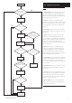
17.0 High Fault Finding Reset NOTE: The fan is supplied with 325 Vdc. Low Fan Fault Finding should only be carried out after the boiler has been electrically isolated. ON Lockout Boiler On Mains On LED Light (Red) LED Light (Green) LED Light (Green) Lights Off Off Off YES General Fault Finding should only be carried out by someone who is appropriately qualified. Go to Electrical Supply section of the fault finding instructions.
Lights Off Off Off ELECTRICAL SUPPLY 17.0 Fault Finding ON NO 240V at A ? No Switched Live to boiler. Check Systems Controls and System Wiring. YES NO 240V at B ? A Check wiring from terminal block to PCB. YES L NO PCB fuse OK ? Check for shorts on pump, fan & gas valve. Replace if shorted & replace fuse. YES Replace PCB.
Lights On Flash Flash 17.0 Fault Finding DRY-FIRE ON Are Flow & Return reversed ? YES Swop Flow & Return. E NO Is the system full of water ? NO Fill system with water and bleed out all air. L N Optional Pump Replace PCB. Live YES YES Turn mains off & on. After 5 sec, is there 240V at E? NO Is the pump running ? YES YES Unplug 5-way PCB connector. Is there continuity between H (run pump from switched live) ? NO Turn mains off, unplug 7-way connector to PCB.
Lights On Off On IGNITION LOCKOUT 17.0 Fault Finding ON I NO Is there gas at gas valve inlet ? Check isolation valve and gas supply. J 5-way Connector YES Remove 5-way connector from gas valve. Is there 240 Vdc between I & J during ignition ? NO Reset Lockout. Is there gas flow (check at meter) ? YES Replace Gas Valve. NO YES Is there at least 18mbar dynamic at gas valve inlet ? NO Remove the larger or the two 6-way PCB connectors.
Lights Flash Off On OVERHEAT LOCKOUT 17.0 Fault Finding ON Disconnect black stat on flow pipe. When flow < 60° C is there continuity across stat ? NO Replace Stat. YES Reconnect stat. Disconnect fan stat. When fan temp < 60° C is there continuity across stat ? NO Replace Stat. YES Reconnect stat. Disconnect the larger of the 6-way PCB connectors. Is there continuity across M ? NO YES Disconnect thermistor (red sensor on flow pipe). Is resistance between 0.
Lights Flash Flash On FAN LOCKOUT 17.0 Fault Finding NOTE: The fan is supplied with 325 Vdc. ON Fan Fault Finding should only be carried out after the boiler has been electrically isolated. Fan Connection Unplug 3-way PCB connector & unplug fan. Is there continuity from N to O & from P to Q ? PCB Connection NO Rectify wiring. O N Q P YES Unplug the smaller of the 6-way PCB connector. Is there continuity from R to S & from T to U & from V to W ? YES Replace fan.
Lights On Flash On THERMISTOR 17.0 Fault Finding ON Unplug thermistor, Is thermistor resistance between 0.5kΩ & 20kΩ ? NO Replace thermistor. D YES Plug in thermistor, leave 8-way connector unplugged. Is resistance at D between 0.5kΩ & 20kΩ ? NO Wiring from PCB to thermistor faulty. Viewed from Wire Entry end YES Replace PCB.
18.
18.
BENCHMARK No. 5 1 2 1 9 0 8 GAS BOILER COMMISSIONING CHECKLIST COLLECTIVE MARK BOILER SERIAL No. NOTIFICATION No.
SERVICE INTERVAL RECORD It is recommended that your heating system is serviced regularly and that you complete the appropriate Service Interval Record Below. Service Provider. Before completing the appropriate Service Interval Record below, please ensure you have carried out the service as described in the boiler manufacturer’s instructions. Always use the manufacturer’s specified spare part when replacing all controls SERVICE 1 DATE SERVICE 2 DATE ENGINEER NAME COMPANY NAME TEL No.
All descriptions and illustrations provided in this leaflet have been carefully prepared but we reserve the right to make changes and improvements in our products which may affect the accuracy of the information contained in this leaflet. All goods are sold subject to our standard Conditions of Sale which are available on request. P O T T E RTON A Trading Division of Baxi Heating UK Ltd (3879156) A divis io n of B a x i Gro u p Brooks House, Coventry Road, Warwick.