BAUMFOLDER CORPORATION Quality Bindery Equipment Since 1917 ND5 DRILL INSTRUCTION & PARTS MANUAL ©Baumfolder Corp., 2000 Printed in U.S.
© BAUMFOLDER CORPORATION 2000 All Rights Reserved WARNING • Do not operate this machine without all guarding in place. • Do not make adjustments or perform maintenance on this machine with power on. • Keep the machine and the work area clean and free of spills to prevent accidents. • Be sure to replace any safety decals that may have been detached for any reason.
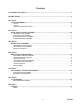
Contents FUNDAMENTAL SAFETY ................................................................................................................ 4 INSTRUCTIONS ................................................................................................................................ 4 SECTION 1: MAIN ASSEMBLIES ............................................................................................................... 1-1 1 PHASE .........................................................................
Carefully remove the wood frame and remove one of the side covers to find these items. Be sure to check off the parts received against the packing list. Examine the machine carefully for any physical signs of shipping damage. ND-5 PAPER DRILL Your new ND-5 Paper Drill has been designed to provide you with years of useful service, provided it is installed, maintained and operated according to the instructions contained in this manual. The machine is fastened to the skid with four bolts.
SETTING DRILL HEADS ELECTRICAL SYSTEM Check the black serial number tag on the left rear corner of the A) Raise the hinged top cover. machine base for voltage/phase/hertz and amperage required. This tag also lists the time delay fuse amperage and the wire B) Insert the drill bits into the drill head spindles. Use drill extensize for the supply conductor. sions on all bits that have a threaded hole in the top end. Check the proper rotation of the drill head drive shaft.
OPERATION A) It is best when setting up a job to begin with the table locked in its center position and work outward from the zero mark on the scales. The zero marks on the drill head scale, table scale, and step bar scale, are all in line when the table is locked in the center position. To lock the table in the center position, turn the knob under the front of the table so that it will slide the plunger up into the hole provided in the tie bar when the hole passes over the plunger.
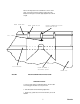
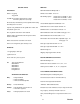
M) Use the impression in the wood block to set the corner guide. Use the back gage bar clamps to adjust the guide knob shown in Figure 1 to make slight adjustments to the left or right. BACK GAGE BAR ROUND CORNERING GUIDE MOUNTING BLOCK BACK GAGE BLOCK ADJ. KNOB WOOD BLOCKS ROUND CORNER & SLOTTING GUIDE TABLE TOP FIGURE 1 ROUND CORNER AND SLOTTING GUIDE IMPORTANT NOTES 1. For best results and to avoid knife breakage, no more than 1/2 inch of paper should be cut at any one time. 2.
7. USE DRILL EXTENSIONS DRILL HEAD AND BIT TIPS Drill extensions help chips flow up into the spindle and out of the ejection slot. There are two sizes of extensions: the black extension fits 1/8" through 5/32" drills; the gray extensions fit 3/16, 7/32, and 1/4" drills. The larger diameter drills do not need extensions. Extensions help prevent drill breakage, especially when drilling coated stock. 1. KEEP DRILLS SHARPENED A dull drill bit can be a major cause of drill bit breakage.
SPECIFICATIONS DRILLING: ELECTRICAL: Maximum number of drilling heads: 5 Motors: 1 hp pump 2 hp spindle Drill bit sizes available: 1/8" to 1/2" Max drilling capacity: Available in:208-22OV/1 phase/60 hz at 20 amps 208-22OV/3 phase/60 hz at 10 amps Electrical safety interlock that prevents spindles from rotating when hinged cover is raised. Separate start pushbuttons for the spindle drive motor and the hydraulic power unit. 5 heads with 1/4 drill bits - 2 max. 4 heads with 3/8" drill bits - 2" max.
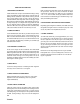
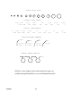
ACTUAL DRILL SIZES DIAMETER: INCHES/(METRIC) 1/8" 5/32" 3/32" 3-1mm 4mm 5mm 7/32" 5-5mm 1/4" 6mm 7mm 9/32" 8mm 5/16" 9mm 11/32" 9- CAPACITY: INCHES/(METRIC) 1" 1-1/8" 1-1/2" 25mm 25mm 35mm 1-3/4" 40mm 50mm 2" 50mm 2" 50mm 2" 50mm SHAPES OF ROUND CORNERS 3/16" R (5mm) 3/8" R (9-5mm) 1/2" R (12-5mm) 45 DEG SLOTTED HOLES PRODUCED Drill bits, corner shaping cutters and slotted hole cutters are available through Baumfolder or your local Baumfolder dealer.
TROUBLESHOOTING PROBLEM 1) Drill heads wont come down POSSIBLE SOLUTIONS a) Check motor rotation of drive shaft with arrow on belt guard. Switch two wires of the incoming electrical cable to correct rotation. b) Relief valve may need adjusting. Contact the BM Dealer or Baumfolder office where you purchased your ND-5 drill for assistance.