BAUMFOLDER CORPORATION Quality Bindery Equipment Since 1917 FLEXIFOLD PILE FEEDER INSTALLATION & OPERATION MANUAL TP10456-EN
© 2004 Baumfolder All Rights Reserved WARNING • Do not operate this machine without all guarding in place. • Do not make adjustments or perform maintenance on this machine with power on. • Keep the machine and the work area clean and free of spills to prevent accidents. • Be sure to replace any safety decals that may have been detached for any reason.
TABLE OF CONTENTS 1.0 FUNDAMENTAL SAFETY INSTRUCTIONS .......................................................................... 5 2.0 INTRODUCTION ........................................................................................................................ 9 3.0 SPECIFICATIONS ....................................................................................................................... 9 4.0 PILE FEEDER & REGISTER INSTALLATION INSTRUCTIONS ....................................... 9 5.
TABLE OF CONTENTS LIST OF TABLES Operator Panel Key Function ............................................................................................................... 17 Operator Panel Indicators ..................................................................................................................... 17 Power Up Fault Messages .................................................................................................................... 21 Run Fault Error Messages ...................
FUNDAMENTAL SAFETY INSTRUCTIONS! The diagrams and descriptions used in these instructions are not necessarily applicable to the specification of the machine supplied. Modifications, made for reasons of technical or operational improvement, are embodied without notice.
1.0.3 FUNDAMENTAL SAFETY INSTRUCTIONS! The machine/installation is designed exclusively for paper finishing of minimum and maximum sheet sizes (see corresponding operating instructions). Using the machine/ installation for purposes other than those mentioned above is considered contrary to its designated use. The manufacturer/supplier cannot be held liable for any damage or injury arising from such misuse. The risk of such misuse lies entirely with the user.
1.1.9 1.3.2.1 Report any accident that occurs due to a malfunction of the machine though all prescribed safety precautions were observed directly to our agency. Always press the emergency (Not-Stop) button first, if you stop the machine for adjustments or maintenance work which must not be done while the machine is in operation. 1.3.2.2 1.2 Selection and qualification of personnel - Basic responsibilities For extensive maintenance or repair work, turn off the main power supply. 1.3.2.3 1.2.
1.4.1.3 Warning! The electrical equipment of machines/plants is to be inspected and checked at regular intervals. Defects such as loose connections or scorched cables must be rectified immediately. To avoid bruising, keep hands away when operating moving machine parts! 1.4.1.4 Necessary work on live parts and elements must be carried out only in the presence of a second person who can cut off the power supply in case of danger by actuating the emergency shut-off or main power switch.
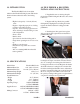
2.0 INTRODUCTION 4.0 PILE FEEDER & REGISTER INSTALLATION INSTRUCTIONS The Flexifold Pile Feeder is a modular addition to the Flexifold Folding System. This feeder has these features that adds value to the folding system. - Higher load capacity - 18 inch (45.8cm) stack - Register - aligns the paper prior to folding for improved folding accuracy.
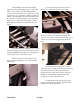
5. Check height of feeder in relationship to register by placing a 1mm thick (approx.) object that will sit on top of register ribs without being held. A common 12 inch scale placed at an angle on top of the register ribs is a good example of what to use. The top surface of the 1mm thick object should be in line with the top surface of rake plate fingers on the pile feeder. Adjust casters on pile feeder accordingly to achieve this height relationship between the pile feeder and register. 8.
5.0 PILE FEEDER & REGISTER SETUP 1. Set the right hand-side guide to half the sheet width using the scale located on the side guide support bar. Lock the side guide in place using the lock lever. 2. Remove the left hand side guide from feeder. 4. Press the Table Down Key on the operator panel, the Pile Feeder Table will travel downwards until it passes the Ergonomic Pile Reload Sensor. switch. It is recommended that there be at least a 1.00-1.25 inch (25.40 - 31.
10. Each side guide has a sheet guide drag block with pins. Each sheet guide drag block has 2 pins. One pin will have a rubber bumper on the lower end, the other will not. Use of the rubber bumpers is dependent on the stock. Use the rubber bumpers to prevent the feeder from pulling doubles on to the register. 11.Using the handwheel, adjust the register gage to approximately 1/6” away from the edge of the paper stack.
14. The register is supplied with 2 short sheet holddowns and 1 long sheet holddown. The 2 short holddowns should always be used. They are placed in front of the sucker wheel guard assembly on the angle braces above the register ribs. The long holddown is used on sheets that require the register gage to be beyond the end of the sucker wheel guard assembly. 15. The pile feeder and register has a double sheet detector designed to stop double sheets from being fed onto the register and being folded.
A. Determine the width of sheets to be folded. B. On side of the operator side guard, there is a blow bar settings chart. Locate the sheet width to be folded on this chart and the position the blow bar is recommended to be set at. Using the numbers on the operator side of the blow bar, set the blow bar to the recommended setting on the chart. This is only a recommendation and may need to be set up differently according to the stock being ran. 18.
A. Pile Height Sensor Sensitvity Adjustment This adjustment is made by turning the pot located on top of the sensor next to the indicator. This will increase or decrease the sensitivity of the sensor. Note: Do not turn the pot adjustment past it stops. Damage to the sensor may result. B. Pile Height Vertical Location Adjustment This adjust can be made by loosening the locking lever holding the sensor in place. The sensor will now be free to move vertically in its retainer.
7.
8.0 OPERATOR PANEL KEY & INDICATOR FUNCTION DESCRIPTIONS 1.) Pile Feeder Stop Key Disables the controller outputs 2.) Pile Feeder Start Key Initiates startup diagnostic and enables controller outputs 3.) Sheet Mode Key Selects between production mode and single sheet mode 4.) Sheet Start Key Initiates feeding of sheets by energizing the vacuum solenoid 5.) Diagnostic Key Initiates the diagnostic program 6.) Reset Key Initiates a reset function for counters or error functions 7.
9.0 PILE FEEDER INITIAL CALIBRATION INSTRUCTIONS The pile feeder is programmed to match the feed rate of the parallel folding unit. However, before the pile feeder can accurately follow the parallel folding unit’s feed rate, the pile feeder must be calibrated to do so. The next few steps listed in this section will explain how to achieve the pile feeder calibration.
10.0 PRODUCTION RUN MODE To initiate production, operate the Feeder ON and load the feeder. 1. Lower the table using the Table Down Key, 8. Note: If the Table Down Key is pressed twice within 0.5 seconds, the table will proceed past the ergonomic pile reload height position and continue until it trips the lower limit switch. 2. Load the Table and raise the Table by holding down the Table Up Key, 10. 3. Start the drive on the 1st Folding Station. 4.
COUNT BATCH XXXXXXXX WWW ZZZZ NOTE: To turn off the Batch Counter, set the Batch Size to zero, 0. 12.0 SINGLE BATCH SETTING The Single Batch Setting will allow the Pile Feeder process a Single Batch to the desired Batch Size each time the Sheet Start Key, 4, is pressed. The following instructions will tell you how to set up the Pile Feeder to run Single Batches at a desired Batch Size. 1. Press the Batch Set Key, 11. The Batch Set screen will be displayed. BATCH DWELL ZZZ Y.
14.0 RESETTING THE TOTAL COUNTER The following instructions will allow you to reset the Total Counter. Note: The Batch Counter will also be reset to zero, 0, when the Total Counter is reset. 1. Press the Reset Key, 5, and the Reset Screen RESET will be displayed. 2. Press the Count Key, 12, and the display will return to the Batch Count Screen with the Batch Counter and the Total Counter reset to zero, 0. 15.
16.0 RUN FAULT ERROR MESSAGES These error messages may occur during setup or a production run. ERROR MESSAGE INHIBIT DOUBLE SHEET REMARKS 1st Station is not running, check wiring to controller board. Remove the double sheet, check sensor, wiring to controller board 17.0 CONTROLLER LED LIST The following is a list of LEDs and their associated circuit located on the controller.
1. Turn the main Pile Feeder Power Switch on. 2. Press the Pile Feeder Start Key, 2. 3. Press the Diagnostic Key, 5. The message DIAGNOSTIC (Y) ENTER (N) RESET will be displayed. 4. Press the Enter Key, 7, to enter the diagnostic tests or press the Reset Key, 5, to exit. The message KEYPAD TESTS PRESS ENTER will be displayed, if Enter Key is pressed. 5. Press the Enter Key, 7, to enter the keyboard tests. The message PRESS TABLE UP KEY INACTIVE will be displayed if Enter Key is pressed. 6.
18.0.2 PILE FEEDER SENSOR TESTS This test will test the operability of each sensor contained in the following table. As each sensor is operated, its status should switch between “INACTIVE” and “ACTIVE”. If the display does not switch from inactive to active when the sensor is operated, something is wrong with the sensor, display assembly, communication cable or controller board. Exiting this Diagnostic program can be done at any time by scrolling to the EXIT screen and pressing the Enter Key, 7. 1.
9. Press the Enter Key, 7, and the operator panel will return to the SENSOR TESTS PRESS ENTER screen. 10. Use the Up Arrow Key, 14, until the message PRESS ENTER TO EXIT TESTS is displayed. 11. Press Enter Key, 7, and the operator panel display will return to the main count screen.
4. Press the Enter Key, 7, to enter the diagnostic tests or press the Reset Key, 5, to exit. The message KEYPAD TESTS PRESS ENTER will be displayed, if Enter Key is pressed. 5. Press the Up Arrow Key, 14, until the message OUTPUT TESTS PRESS ENTER is displayed. 6. Press the Enter Key, 7, and the message FEED WHEEL TEST VERIFY OFF will be displayed. 7. Using the Up/Down Arrow Keys, 14/13, select the output test of interest.
OUTPUT 1 FEED WHEEL TEST 2 FEED SOLENOID TEST 3 STOP SOLENOID TEST REMARKS The Feed Wheel should turn on when entering this test and turn off when the arrow keys are used to select another test. If the Feed Wheel is not rotating, verify the motor wiring and check dc motor control The Feed Solenoid should energize when entering this test and turn off when the arrow keys are used to select another test. If the Feed Solenoid does not energize, check solenoid wiring and voltage (12 Vdc).
The Batch Output Indicator, 17, should be flashing on and off. Also, The text in the display on the Operator Panel should be switching from “OFF” and “on” in relation with the Batch Output Indicator. This also appiles to each indicator listed in the Indicator Test Table. 7. Using the Up/Down Arrow Keys, 14/13, select the output test of interest.
PAGE 29 TP10456-EN