FLEXIFOLD PILE FEEDER INSTALLATION & OPERATION MANUAL FOR INSTRUCTION MANUALS IN GERMAN, SPANISH AND FRENCH GO TO WWW.BAUMFOLDER.
© 2004 Baumfolder All Rights Reserved WARNING • Do not operate this machine without all guarding in place. • Do not make adjustments or perform maintenance on this machine with power on. • Keep the machine and the work area clean and free of spills to prevent accidents. • Be sure to replace any safety decals that may have been detached for any reason.
TABLE OF CONTENTS 1.0 FUNDAMENTAL SAFETY INSTRUCTIONS .........................................................................5 2.0 INTRODUCTION ......................................................................................................................21 3.0 SPECIFICATIONS .....................................................................................................................21 4.0 PILE FEEDER & REGISTER INSTALLATION INSTRUCTIONS ...................................21 5.
TABLE OF CONTENTS LIST OF TABLES Operator Panel Key Function...............................................................................................................29 Operator Panel Indicators ....................................................................................................................29 Power Up Fault Messages....................................................................................................................33 Run Fault Error Messages..........................
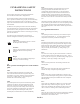
FUNDAMENTAL SAFETY INSTRUCTIONS! The diagrams and descriptions used in these instructions are not necessarily applicable to the specification of the machine supplied. Modifications, made for reasons of technical or operational improvement, are embodied without notice.
FUNDAMENTAL SAFETY INSTRUCTIONS! 1.0.3 These operating instructions are designed to familiarize the user with the machine and its designated use. The instruction manual contains important information on how to operate the machine safely, properly and most efficiently. Observing these instructions helps to avoid danger, to reduce repair costs and downtimes and to increase the reliability and life of the machine.
1.1.9 Report any accident that occurs due to a malfunction of the machine though all prescribed safety precautions were observed directly to our agency. 1.2 Selection and qualification of personnel - Basic responsibilities 1.3.2.1 Always press the emergency (Not-Stop) button first, if you stop the machine for adjustments or maintenance work which must not be done while the machine is in operation. 1.3.2.2 For extensive maintenance or repair work, turn off the main power supply. 1.3.2.3 1.2.
1.4.1.3 Warning! The electrical equipment of machines/plants is to be inspected and checked at regular intervals. Defects such as loose connections or scorched cables must be rectified immediately. To avoid bruising, keep hands away when operating moving machine parts! 1.4.1.4 Necessary work on live parts and elements must be carried out only in the presence of a second person who can cut off the power supply in case of danger by actuating the emergency shut-off or main power switch.
GRUNDLEGENDE SICHERHEITSHINWEISE! Die in diesen Hinweisen verwendeten Diagramme und Beschreibungen gelten nicht notwendigerweise für die gelieferte Maschine. Änderungen, die aus technischen Gründen oder für einen verbesserten Betrieb durchgeführt wurden, werden ohne Vorankündigung übernommen.
GRUNDLEGENDE SICHER HEITSHINWEISE! Die vorliegende Bedienungsanleitung dient dazu, dass sich der Anwender mit der Maschine und deren Einsatzzweck vertraut macht. Die Bedienungsanleitung enthält wichtige Informationen über den sicheren, bestimmungsgemäßen und wirkungsvollen Betrieb der Maschine. Bei Beachtung dieser Anweisungen werden Gefahren vermieden, Reparaturkosten und Stillstandszeiten verringert sowie die Zuverlässigkeit und die Lebensdauer der Maschine erhöht.
1.1.8 Ersatzteile müssen die vom Hersteller festgelegten technischen Anforderungen erfüllen. Stammen Ersatzteilen von OEM-Herstellern, kann davon ausgegangen werden, dass diese Anforderungen erfüllt werden. 1.1.9 Unserer Vertretung jeglichen Unfall sofort melden, zu dem es aufgrund einer Störung der Maschine gekommen ist, obwohl alle vorgeschriebenen Sicherheitsmaßnahmen beachtet wurden. 1.
1.4.1 Elektrische Energie 1.4.1.1 Nur Original-Sicherungen mit der angegebenen Nennleistung verwenden. Die Maschine/Anlage sofort ausschalten, falls es zu Störungen im elektrischen System kommt. 1.5 Beschreibung und Definition der Sicherheitsaufkleber und Piktogramme auf der Maschine Beschädigte Piktogramme durch neue ersetzen. Die entsprechenden Referenznummern sind angegeben. 1.4.1.
INSTRUCTIONS FONDAMENTALES SUR LA SÉCURITÉ Les schémas et les descriptions utilisés au cours de ces instructions ne sont pas nécessairement applicables aux spécifications de la machine fournie. Les modifications, réalisées pour des motifs techniques ou d’amélioration du fonctionnement sont intégrées sans avis préalable.
INSTRUCTIONS FONDAMENTALES SUR LA SÉCURITÉ qu’implique le fonctionnement de la machine/de l’installation. Tous défauts fonctionnels, particulièrement ceux pouvant affecter la sécurité de la machine/l’installation, doivent être de ce fait immédiatement réparés. Ces instructions de fonctionnement sont conçues afin de familiariser l’utilisateur avec la machine et l’utilisation pour laquelle elle a été conçue.
1.1.7 Ne procédez jamais à aucune modification, ajout ou transformation qui pourrait affecter la sécurité sans l’approbation du fournisseur. Ceci s’applique aussi à l’installation et au réglage des dispositifs et des vannes de sécurité ainsi que des soudures sur les éléments porteurs. 1.1.8 Les pièces détachées doivent être conformes aux spécifications techniques publiées par le fabricant. Les pièces détachées d’origine des fabricants de l’équipement peuvent être utilisées en toute confiance. 1.1.
1.3.2.8 Veuillez informer le personnel d’exploitation avant de commencer des opérations spéciales ou de maintenance, et désignez une personne pour surveiller ces tâches. male requise pour cette plieuse est de 25 A. 1.3.2.
INSTRUCCIONES FUNDAMENTALES DE SEGURIDAD Los diagramas y descripciones que se utilizan en estas instrucciones no son necesariamente aplicables a la especificación de la máquina suministrada. Las modificaciones hechas con el fin de introducir mejoras técnicas o de funcionamiento se incorporan sin aviso.
INSTRUCCIONES FUNDAMENTALES DE SEGURIDAD Estas instrucciones de funcionamiento están diseñadas para que el usuario se familiarice con la máquina y su uso indicado. El manual de instrucciones contiene información importante sobre cómo manejar la máquina de manera segura, correcta y eficaz. La observación de estas instrucciones contribuirá a evitar peligros, reducir el coste de las reparaciones y los tiempos de inactividad, y aumentar la fiabilidad y la vida útil de la máquina.
1.1.9 Notifique directamente a nuestra agencia cualquier accidente que se produzca debido a un mal funcionamiento de la máquina, pese a haberse observado todas las precauciones de seguridad prescritas. 1.2 Selección y cualificación del personal – Responsabilidades básicas 1.2.1 Emplee únicamente personal entrenado o instruido y exponga claramente las responsabilidades individuales del personal en cuanto al manejo, instalación, mantenimiento y reparación.
1.4.1.3 El equipo eléctrico de máquinas/plantas debe inspeccionarse y controlarse a intervalos regulares. Los defectos como conexiones sueltas o cables quemados deben corregirse inmediatamente. Advertencia Para evitar magulladuras, mantenga las manos alejadas al manejar las piezas móviles de la máquina. Advertencia 1.4.1.
2.0 INTRODUCTION 4.0 PILE FEEDER & REGISTER INSTALLATION INSTRUCTIONS The Flexifold Pile Feeder is a modular addition to the Flexifold Folding System. This feeder has these features that adds value to the folding system. 1. If applicable, remove existing short pile feeder from parallel folding unit. Be sure to disconnect both hoses. - Higher load capacity - 18 inch (45.8cm) stack - Register - aligns the paper prior to folding for improved folding accuracy.
5. Check height of feeder in relationship to register by placing a 1mm thick (approx.) object that will sit on top of register ribs without being held. A common 12 inch scale placed at an angle on top of the register ribs is a good example of what to use. The top surface of the 1mm thick object should be in line with the top surface of rake plate fingers on the pile feeder. Adjust casters on pile feeder accordingly to achieve this height relationship between the pile feeder and register. 8.
5.0 PILE FEEDER & REGISTER SETUP 1. Set the right hand-side guide to half the sheet width using the scale located on the side guide support bar. Lock the side guide in place using the lock lever. feeder. 2. Remove the left hand side guide from 4. Press the Table Down Key on the operator panel, the Pile Feeder Table will travel downwards until it passes the Ergonomic Pile Reload Sensor. 5. Load the paper onto the feed table, using the spreader plate and right hand side guide as stops.
10. Each side guide has a sheet guide drag block with pins. Each sheet guide drag block has 2 pins. One pin will have a rubber bumper on the lower end, the other will not. Use of the rubber bumpers is dependent on the stock. Use the rubber bumpers to prevent the feeder from pulling doubles on to the register. 11.Using the handwheel, adjust the register gage to approximately 1/6” away from the edge of the paper stack.
14. The register is supplied with 2 short sheet holddowns and 1 long sheet holddown. The 2 short holddowns should always be used. They are placed in front of the sucker wheel guard assembly on the angle braces above the register ribs. The long holddown is used on sheets that require the register gage to be beyond the end of the sucker wheel guard assembly. 15. The pile feeder and register has a double sheet detector designed to stop double sheets from being fed onto the register and being folded.
folded. A. Determine the width of sheets to be B. On side of the operator side guard, there is a blow bar settings chart. Locate the sheet width to be folded on this chart and the position the blow bar is recommended to be set at. Using the numbers on the operator side of the blow bar, set the blow bar to the recommended setting on the chart. This is only a recommendation and may need to be set up differently according to the stock being ran. 18.
A. Pile Height Sensor Sensitvity Adjustment - This adjustment is made by turning the pot located on top of the sensor next to the indicator. This will increase or decrease the sensitivity of the sensor. Note: Do not turn the pot adjustment past it stops. Damage to the sensor may result. LANGUAGE SELECTION Dip switches found on the CPU Board 115 VOLT ENGLISH B. Pile Height Vertical Location Adjustment - This adjust can be made by loosening the locking lever holding the sensor in place.
7.
8.0 OPERATOR PANEL KEY & INDICATOR FUNCTION DESCRIPTIONS 1.) Pile Feeder Stop Key Disables the controller outputs 2.) Pile Feeder Start Key Initiates startup diagnostic and enables controller outputs 3.) Sheet Mode Key Selects between production mode and single sheet mode 4.) Sheet Start Key Initiates feeding of sheets by energizing the vacuum solenoid 5.) Diagnostic Key Initiates the diagnostic program 6.) Reset Key Initiates a reset function for counters or error functions 7.
9.0 PILE FEEDER INITIAL CALIBRATION INSTRUCTIONS The pile feeder is programmed to match the feed rate of the parallel folding unit. However, before the pile feeder can accurately follow the parallel folding unit’s feed rate, the pile feeder must be calibrated to do so. The next few steps listed in this section will explain how to achieve the pile feeder calibration.
10.0 PRODUCTION RUN MODE To initiate production, operate the Feeder ON and load the feeder. 1. Lower the table using the Table Down Key, 8. Note: If the Table Down Key is pressed twice within 0.5 seconds, the table will proceed past the ergonomic pile reload height position and continue until it trips the lower limit switch. 2. Load the Table and raise the Table by holding down the Table Up Key, 10. 3. Start the drive on the 1st Folding Station. 4.
NOTE: To turn off the Batch Counter, set the Batch Size to zero, 0. 12.0 SINGLE BATCH SETTING The Single Batch Setting will allow the Pile Feeder process a Single Batch to the desired Batch Size each time the Sheet Start Key, 4, is pressed. The following instructions will tell you how to set up the Pile Feeder to run Single Batches at a desired Batch Size. 1. Press the Batch Set Key, 11. The Batch Set screen will be displayed. The Z digits (flashing) are the batch size.
14.0 RESETTING THE TOTAL COUNTER The following instructions will allow you to reset the Total Counter. Note: The Batch Counter will also be reset to zero, 0, when the Total Counter is reset. 1. Press the Reset Key, 5, and the Reset Screen will be displayed. 2. Press the Count Key, 12, and the display will return to the Batch Count Screen with the Batch Counter and the Total Counter reset to zero, 0. 15.
16.0 RUN FAULT ERROR MESSAGES These error messages may occur during setup or a production run. 17.0 CONTROLLER LED LIST The following is a list of LEDs and their associated circuit located on the controller. 18.0 DIAGNOSTIC PROGRAM The diagnostic program contains several routines that will test the operator keypad, test the controller sensors, test the controller output circuits and test the panel indicators. 18.0.
1. Turn the main Pile Feeder Power Switch on. 2. Press the Pile Feeder Start Key, 2. 3. Press the Diagnostic Key, 5. The message will be displayed. 4. Press the Enter Key, 7, to enter the diagnostic tests or press the Reset Key, 5, to exit. The message 5. Press the Enter Key, 7, to enter the keyboard tests. The message will be displayed if Enter Key is pressed. 6. Press the Table Up Key, 10, and the display should switch between to “ACTIVE” each time the Table Up Key is pressed.
18.0.2 PILE FEEDER SENSOR TESTS This test will test the operability of each sensor contained in the following table. As each sensor is operated, its status should switch between “INACTIVE” and “ACTIVE”. If the display does not switch from inactive to active when the sensor is operated, something is wrong with the sensor, display assembly, communication cable or controller board. Exiting this Diagnostic program can be done at any time by scrolling to the EXIT screen and pressing the Enter Key, 7. 1.
9. Press the Enter Key, 7, and the operator panel will return to the screen. 10. Use the Up Arrow Key, 14, until the message is displayed. 11. Press Enter Key, 7, and the operator panel display will return to the main count screen. 18.0.3 PILE FEEDER OUTPUT TESTS This group of tests will help to verify the operation of the output circuits contained in the Output Circuit Test table. Exiting this Diagnostic program can be done at any time by scrolling to the EXIT screen and pressing the Enter Key, 7. 1.
4. Press the Enter Key, 7, to enter the diagnostic tests or press the Reset Key, 5, to exit. The message 5. Press the Up Arrow Key, 14, until the message is displayed. 6. Press the Enter Key, 7, and the message will be displayed. 7. Using the Up/Down Arrow Keys, 14/13, select the output test of interest. In the table on the next page, there is a list of each output test available in this diagnostic program, along with remarks on how the chosen output should function normally. 8.
18.0.4 PILE FEEDER INDICATOR TESTS These tests will test the operation of the each indicator on the operator panel. Exiting this Diagnostic program can be done at any time by scrolling to the EXIT screen and pressing the Enter Key, 7. 1. Turn the main Pile Feeder Power Switch on. 2. Press the Pile Feeder Start Key, 2. 3. Press the Diagnostic Key, 5. The message 4. Press the Enter Key, 7, to enter the diagnostic tests or press the Reset Key, 5, to exit. The message 5.
The Batch Output Indicator, 17, should be flashing on and off. Also, The text in the display on the Operator Panel should be switching from “OFF” and “on” in relation with the Batch Output Indicator. This also appiles to each indicator listed in the Indicator Test Table. 7. Using the Up/Down Arrow Keys, 14/13, select the output test of interest.
Baumfolder has authorized dealers located throughout the United States. Call toll free, 1-800/543-6107 for parts or the number of your nearest authorized dealer. BAUM BAUMFOLDER CORPORATION 1660 Campbell Road Sidney, Ohio 45365-0728 Phone: 937/492-1281 or 800/543-6107 Fax: 800/452-0947 Internet: www.baumfolder.com E-mail: baumfolder@baumfolder.