BAUM BAUM 2020 1ST STATION FOLDER W/PILE FEED INSTRUCTION MANUAL ©Baumfolder Corp., 2006 Printed in U.S.A.
© 2006 BAUMFOLDER CORPORATION All Rights Reserved WARNING • Do not operate this machine without all guarding in place. • Do not make adjustments or perform maintenance on this machine with power on. • Keep the machine and the work area clean and free of spills to prevent accidents. • Be sure to replace any safety decals that may have been detached for any reason.
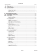
CONTENTS DESCRIPTION PAGE I.) II.) III.) IV.) V.) Safety .................................................................................................................................................................. 6 Introduction Overview ........................................................................................................................................ 7 Transportation/Installation ..................................................................................................
CONTENTS DESCRIPTION IX.) X.) XI. ) XII.) XIII.) XIV.) XV.) XVI.) XVII.) XVIII.) XIX.) XX.) XXI.) XXII.) XXIIi.) XXIV.) XXV.) XXVI.) XXVII.) PAGE Pile Feeder Operation ...................................................................................................................................... 37 1.0 . Loading ............................................................................................................................................... 37 1.1 . Hold-down Locations ..............
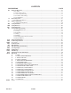
List of Tables DESCRIPTION PAGE Table 1. Machine Setup Parameter List "A" ........................................................................................................................ 24 Table 2. Machine Monitor Parameter List ............................................................................................................................ 24 Table 3. Machine Setup Parameter List "B" ......................................................................................................
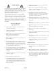
10. Make sure that all safety devices are in place before restarting the machine. SAFETY FIRST Your new Baum paper folding machine has been designed in accordance with the latest safety specifications. The warning and caution labels on the machine must remain in place. Make sure all guarding provided is in place before starting up and running the machine.
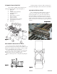
INTRODUCTION OVERVIEW The 1st station [parallel] folder with pile feeder contains the following main components (Figure 1): 1. Pile Feeder 2. Register 3. 1st Station Folder (Parallel) 4. Fold Roller Gapsets 5. Fold Plates 6. Slitter Shafts (not shown) 7. Delivery (Stacker) 8. Operator Controls 9. Double Sheet Detector (Caliper) 10. Vacuum Pump (not shown) 11. Handwheel Figure 1 Level the machine on the floor. Place a spirit level on the #2 fold roller (Figure 3) and on the feeder crossmembers.
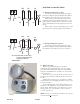
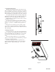
W2 U2 ELECTRICAL CONNECTIONS V2 GND #4 #5 U1 V1 #1 W1 #2 W2 U2 V2 #3 U1 #1 1.1 Wiring the Pump (2020 / 1 phase) Connect the pressure/vacuum pump at the pump junction box (Figure 5) using the attached cable. Follow the instructions to the left for the proper connections. GND V1 #4 G/Y #3 1.0 Wiring the Pump (2020 / 3 phase) Connect the pressure/vacuum pump at the pump junction box (Figure 5) using the attached cable. Follow the instructions to the left for the proper connections.
1.3 Tapping the Transformer Pass the power cable through the strain relief and the hole provided in the control box. Connect the power cable to the open terminals on the main disconnect in the control box. The incoming ground wire should be attached to the ground stud located in the lower right-hand corner of the control box. To tap the transformer, read the incoming voltage at the main disconnect. Then move the wire numbered 11L1 on the transformer to the corresponding tap on the transformer.
BAUMFOLDER 2000 Series “QUICK START” INSTRUCTIONS TURNING THE MAIN SWITCH ON When you turn on the Main Power Switch located on the side of the Control Box , you must let the Control automatically run a self-test. During the self-test DO NOT Press any buttons. Pressing of a button will cause an Error Message to appear in the Main Display. To CLEAR Message turn Power OFF at the Main Power Switch—WAIT 5 SECONDS, then turn Power back on. 1. Turn on Main Power Switch on left side of control enclosure.
Then Press the GREEN Button to lower Pile Feed Table. The Table will lower and stop automatically in its lowest position. STARTING PRODUCTION WITH THE BAUM 2020 1. To START the Folder Drive, Press the GREEN Button on the Control Panel just ABOVE the come on. 2.
The Easy-Mode is used for folds that require half of the sheet length or less going into the foldplate. These folding applications normally operate with a 1.0 Inch sheet gap. If you are folding half of the sheet length or more into the foldplate you must have a greater gap. TURN THE EASY-PARAMETER ON/OFF 1. Press the Machine Setup button found in the top row. 2. .Press the Sheet Gap + or - Buttons until P20 appears in the sheet gap display. 3.
4. Look to the right hand end of the counter display. If an “ 1 “ appears in the display the EasyParameter is turned on. If an “ 0 “ is displayed, the Easy-Parameter is turned off, see Figure E1. To turn the Easy-Parameter on or off, Press the Plus (+) button for the batch time delay setup. Pressing this button changes the “ 1 “ to an “ 0 “ and back. This button is found at the far right side of the top row, see Figure E1. 5. Press the gramming mode.
SELECT CONTINUOUS CYCLE MODE It is recommended to use the continuous cycle mode when the job requires more than ½ of the sheet length to go in the #1 fold plate or if the product has a window that will be sensed as the trailing edge of the sheet. The continuous cycle mode allows you to select the SHEET GAP, SHEET LENGTH and the SUCTION LENGTH. Pressing this button enables the selection of either the EASY mode or cYcL mode + Pressing these buttons will toggle between the EASY mode or cYcL mode.
TO START FEEDING 1. Press the GREEN Button to START the Folder Drive and the Pump. 2. Press the GREEN Button ABOVE the symbol to START the Vacuum Solenoid. The Sucker Wheel will pull a sheet from the Feeder onto the Register. TO STOP FEEDING 1. Press the RED Button BELOW the symbol. This will turn the Vacuum Solenoid OFF. The Sucker Wheel will STOP pulling sheets—BUT the Folder Drive and the Pump will stay ON. NOTE: You can also STOP feeding by Pressing the RED PILE FEEDER STOP BUTTON.
EXAMPLE: Hold the MINUS Button, this will automatically count back to P00 (group P0). Now by Pressing the Button will take you to the next Parameter Group P10 – P20 - P30 – P40 – P50 – P60 2. Pressing and directly UNDER the left 3 digits of the Large 8 digit display, this will select the individual Parameters in a select group. EXAMPLE: Start with the first Group of Parameters, the 3 digit display reads P00.
PAGE 17 TP10243-4
To get out of the Machine Parameter Settings Mode, Press return to normal operations. again. The displays will BATCH COUNTING SETUP To enter Batch Count Set-Up, Press 1. This will bring up 3 display functions on the Control Panel. First is the Small 3 digit display – this display must show ood If the display shows any other Mode, the Batch Counter will not function. To change, Press the or Buttons directly UNDER the 3 digit display to change this Mode of Operation.
the or Buttons directly UNDER the 2 digit display until the desired delay number is displayed. EXAMPLE: This is set-up for 10 pieces in a Batch with a 1.5 second delay between Batches. 3. To return back to RUN mode, Press Button and set either the Batch Size or Time Delay to Zero and the Folder will run continuously. STOP FEED In Batch Count Mode, you also can have the Feeder Set-Up for a Stop Feed Count.
RESETTING THE TOTAL COUNTER To reset the Total Counter, Press Button ; ensure the red LED is illuminated. Press Button and HOLD DOWN for 3 SECONDS, The Large 8 digit display will begin to Count BACKWARDS from 5.4.3.2.1, then display CLEARED, the Counter is then ZERO. You MUST Press and HOLD Button as the display is counting BACKWARDS, if at anytime the display the Last Count Value ZERO Button is released, the Counter will NOTE The Batch counte r will also be reset to 0 by this procedure.
INSTALLING FOLD PLATES & STACKER DELIVERY OPERATOR CONTROLS The main operator control panel (Figure 8) is located at the pile feeder. See the "Control Panel" section for a detailed Install the fold plates into the folder. When installing description of all the buttons. the fold plates, take note of the symbol on the fold plate stop (Figure 7-1). The swing deflector may only be brought 1.
1.0 Control Panel BAN-5 17 8 12 10 14 24 2 25 28 1 29 + 4 5 30 32 33 + + 6 0 h 7 3 8 2 9 1 31 + 10 BAUMFOLDER CORPORATION 36 9 13 11 16 15 26 27 3 22 18 23 19 4 20 5 21 7 34 6 35 Figure 1. Control Panel. 1.1 Displays 06) Input Indicator The input indicator shows the status of the suction photo-eye. 01) Large Display Eight digit multi use display composed of 7segment LED’s. 02) Small Display Three digit multi use display composed of 7segment LED’s.
1.4 Keypad Buttons with Selection Indicators 18) 19) 20) 21) 22) 23) Show Output Count Show Batch Count and Number of Batches Show Current Rate Show Input Count Learn Mode Make Ready Mode 1.
2.1.1 Machine Setup Parameters Parameter P00 P01 P02 P03 Function Input Factor Output Factor Tremat Knife Type Setup Variables Setup Variables Setup Variables Setup Variables Adjustable Adjustable Adjustable Adjustable Variable Displayed 1-24 1 to Input Factor 1 or 0 1 or 0 Table 1.
2.1.
P28: Serial Output Type This selection, in maintenance mode, shows selected serial output type. 2.1.4 Diagnostic Parameters P30 P31 P32 P33 P34 P35 Status Input Port 1 P30.1 P30.2 Pile Motor Function Energized Control K1 Status Input Port 2 P31.1 P31.2 Pile Sensor Double Sheet Fault P30.3 Pile Down Button P30.4 Pile Stop Button P30.5 Pile Up Button P30.6 P30.7 P30.8 Compress. Compress. Drive Start Stop Button Start Button Relay K3 P31.3 Pile Bottom P31.4 Sheet Start Button P31.
2.1.6 Machine UsageStatus Parameters # P50 P51 P52 Function Power on time Machine run time Total Input Sheets Type Machine Status Machine Status Machine Status Table 6. Machine Usage Status Parameter List P50: Power On Time This selection shows the time in 1/100 hour during the main switch of the machine is on. P51: Machine Run Time This selection shows the time in 1/100 hour during the main drive contactor of the machine is on.
Batching Time Adjustment + + The batching time adjustments allow the user to select the time duration associated with the currently selected output type. Two output types and times are available. 1. Feed interrupt has a range of 0.0 to 9.9 seconds. 2. Speed-up Table has a range of 0.00 to 5.00 seconds. Pressing these buttons will toggle between the EASY mode or cYcL mode. Set EASY in the large display and press again.
If P06 is set to 0 (no knife is active) and 10 cm /4.0 inches. If P06 is setting to 1, knifes are active. Select Suction Mode + These keys toggle between automatic control and cycle mode. In the cycle mode, the suction valve will be on for the suction length and off for the remainder of the sheet length plus the gap length. No adjustments are made for slipped sheets or process changes.
Exit Make Ready Mode 2.7 Production Mode Enter Run Mode and Select Large Display Content h 0 h Pressing any of these keys will cause the controller to change to a new mode. 2.6 Network Job Mode These keys do not operate as mode select keys in counter setup. In all other modes, the keys both select the large display (1) contents and place the counter into run mode. Pushing one of the buttons will light the button’s associated LED and cause the parameter to be displayed.
Reset Function 0 Pressing and holding this key will result in a reset function being activated after a 5-second countdown. The function is based on the current large display selection, see table 12. The large display (1) will show countdown to reset in this manner. When the button is pressed the message ‘CLr In 5’ will show on the large display (1).
4.0 The Current Rate is rounded to the nearest hundreds. Current Rate can range from 0 to 99,999,900. This process variable is not stored in memory. Process Variables Definitions 4.1 Total Input Count Total Input Count increments by the factor setting each time an input is received at the Input Count input. Total Input Count can range from 0 to 99,999,999. This process variable is stored in memory in case of a power outage. Reset job will clear this process variable to zero. 4.
5.3 Batch Output Time This parameter, accessible in the Batch Setup mode, specifies the output duration or delay that will be used when the Batch Count Down reaches zero. Available ranges are determined by the Batch Output Type selected. The Table below shows the ranges for each output type. Output Delay Duration Type Min. Time Max. Time Feed Not applicable Table 0.000 Sec. 1.000 Sec. Delivery 0.000 Sec. 1.000 Sec. Speed Not applicable Table 15. Output Delay and Duration Min. Time Max. Time 0.0 Sec. 9.
6.0 System Messages and Run Messages 6.1 Power-Up Fault Messages Messages that are displayed during power on self-test. If PLC System Errors are shown in the display, call service.
6.2 Run Time Fault Messages Run time fault messages are only displayed when the unit is in Run mode. Fault errors can still occur, but the corresponding fault message will not be displayed until the unit is switched to Run mode. Run time fault messages are PLC System Errors or errors in the whole Electric System. It is necessary to call a technician or service. ENGLISH DCT X.X.X GERMAN DCT X.X.X CODES TYPE DCT X.X.
6.3 Machine Run Error Messages Machine Run Error Messages help the operator to indicate a production problem. ENGLISH Stop GERMAN Stop1 CODES Stop1 TYPE Information Wrng Sht Fehlerbg Stop2 Machine Run Error 2 Sheet Doppelbg Stop3 Machine Run Error No Feed Bog.Fehl Stop4 Machine Run Error Feeder Sensor Stop5 Long Sht Bg.
PILE FEEDER OPERATION 2 4 3 1.0 Loading the Pile Feeder Set the right hand side guide (Figure 11-1) to half the sheet using the scale (11-2). The vacuum wheel is in the center of the sheet. Lock the guide in place using the lever (11-3). Remove the left hand guide (Figure 12-4) from the feeder. Move the sheet drag guide block (12-5) on the righthand guide to the rear of the paper stock. Press the table down button (for controls, see page 8).
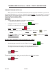
1.3 FRONT BLOW TUBE SETTINGS The front blow consists of two tubes (Figure 13-1 & 2 and Figure 15-1 & 2) instead of the traditional one tube. The numbers on the left hand side of the tubes correspond to the chart (Figure 15-3) found on the side of the main control enclosure. Setting Up 1.) Determine the width of the job to be run. 2.) Find the numbers on the right-hand side of chart that correspond with the sheet width. 3.
The fluted knob (19-6) provides microadjust-ment of the side guide (19-2). Knurled knobs (19-7) provide bias adjustment for the side guide for adjusting sheets that are not square or for other unusual conditions. The double sheet control (Figure 20) is adjusted to the thickness of the paper being fed by pulling up the lever (201) and inserting two paper strips (20-2) of the sheets to be folded in the clip at the back of the lever.
With single sheet thickness, the scanner remains untouched and sheets move freely. A double sheet strikes the scanner on the microswitch, interrupting the sheet flow-through. BAUMSET ADJUSTMENT Figure 21 1.0 Adjustment of Folding Rollers Folding accuracy is determined largely by precise adjustment of the folding rollers. Using the Baumset precision adjustment device, the correct setting of the rollers can be made simply by inserting the appropriate paper thickness between the adjustment plates.
SETTING OF FOLD PLATES NOTE: Check the symbols on the fold plate stop (Figure 23-1) for installation of the fold plate swing deflectors (Figure 24-1) to avoid damaging the fold rollers. The deflector must only be brought forward when the stop (23-1) with the deflector symbol is in the forward position. 5 6 4 Be sure that the adjustment screw (23-2) is in contact with the support rail on both sides. Clamp the fold plates with the clamping screw (Figure 23-3).
Check that the adjustment screws (26-4) are in contact with the support rail (26-5) on both sides. The basic position is marked by a notch (26-6) in the fold-plate frame. Setting Stationary Deflector (Separate sheet deflector) (Figure 27-1) The stationary sheet deflectors are installed and clamped in place in the same way as the fold plates. NOTE: The fold plates in an 8-page folder will work in the #4 fold plate position when four plates are desired.
SCORING/SLITTING/PERFING Your new folder is capable of many different applications that compliment the folding performance and provide for greater productivity. The folder is equipped with slitter shafts that are quickly set up for the required operation. These shafts accommodate the mounting of the standard and optional accessories available that perform scoring, slitting and perforating functions. 1.
1.1 Scoring The folder can be used to score a sheet and deliver it flat, or to score a sheet after a fold or folds have been made. To ensure accuracy in making right angle folds, always score the sheet where the fold or folds are to be made. This applies in all instances when a perforator cannot be used. Various weights of stock with few or numerous folds require a different type of score.
1.2 Perforating The folder may be used for perforating either the heads of booklets (to allow the air to escape in making right-angle folds) or to slot perforate sheets delivered flat, using blades and strippers best adapted for a particular job. All perforating blades are mounted on the upper shaft and run a side of the steel collar on the lower shaft with the flat side of the blade just touching the anvil.
1.3 Slitting (Cutting) Sheets Folders may be used to cut folded or flat sheets apart. Two or more cuts may be made if duplicate sets of slitters are used. Be careful when mounting slitter blades to collars in order to avoid ragged edges which can be caused by two conditions: 1) Nicks or burrs on the collars or blades. Remove carefully by filing or using a fine piece of emery cloth. 2) Incorrect mounting of blades.
1.4 Trimming Edges of Booklets Figure 30 shows the setup of cutting blades and strippers for trimming edges of booklets or outer edges of circulars running two or more up. Cutting blades are attached to blade holder collars so that the bevel of blades on the upper shaft are directed toward the strip being trimmed and the bevel of blades on the lower shaft are directed away from the strip. Blades mounted in this manner tend to turn trimmed edges down which helps guide them to the floor.
1.5 Trimming a Strip from Center of Sheet Figure 31 shows the setup for taking a quarter inch trim out of the center of a sheet. Two or more trims may be made as long as duplicate sets of cutters and strippers are used and this setup adhered to. A strip three sixteenths of an inch wide is the minimum trim. This is the thickness of two of the cutting blades placed together and attached to a blade holder collar. Blades on the upper shaft, for all trims up to one-quarter inch, are attached to one collar.
Center Trimming Spacers for setting width of strip Slitting Blades are located tight against the sharp, flat side of the anvil. Note: Grooves in lower scoring collar are NOT used for slitting or perforating Center stripper wire. Lay wire in center groove and twist ends together at the bottom. Wire floats free and attracts center waste and directs it to the floor Center trim stripping collar.
LUBRICATION/MAINTENANCE Pile Feeder Vacuum Solenoid Valve Figure 32 The vacuum at the suction wheel is controlled by a solenoid valve (Figure 32). This can be quickly and easily removed to clean the piston by loosening the clamping springs. Be careful not to damage the piston and cylinder. See Figure 17. Gear Reducer Check fluid level annually. Check for wear. Refer to parts manual for part number. O-Rings (on vacuum wheel) See Figure 18.
TECHNICAL SPECIFICATIONS BAUM 2020 Maximum sheet size 20.5" x 31" [52 x 78.7cm] Minimum sheet size 4" x 6" [10.1 x 15.2cm] Maximum folder speed 8200 ipm [208m/min] Maximum pile height 25" [63.5cm] Minimum fold length 1.57" [40mm] Maximum fold length 20.5" [52cm] (parallel folder) Slitter shaft diameter 1 1/8" [28.
TROUBLESHOOTING PROBLEM CAUSE REMEDY Sheets stick together particularly along sides. Inadequate ink drying, cut with blunt guillotine blade. Fan out thoroughly when piling, increase blower air. Suction wheels picks up double sheets. Sheets stick together Excessive suction. Air blow improperly set Reduce vacuum setting. Increase air blow Double sheet stop reacts to single sheets. Set only to single paper thickness. Correct to double paper thickness. Tighten lock nut.
TROUBLESHOOTING - continued PROBLEM CAUSE REMEDY Sheets fails to re-emerge from buckle plate. Product too thick for folding. Consult Baum technical rep. Not enough roll pressures. Check Baumset settings. Electrostatic charge in product caused by friction with rollers and deflectors and also relatively low humidity. Fit discharge unit at the exit to the 1st station or arrange for appropriate humidity on the premises. Damping rods and sheet holder set too low. Raise as necessary.
screws for the slitter shaft accessories facing out, so you don't have to turn the shafts to get to the screws. OPERATING TIPS Setup When setting up a job on your folder, watch so the sheet doesn't end up with either the RH or LH edge along the edge of a fold pan or register plate. This could kick it over causing inaccurate folding. TIPS FOR FOLDING The following section contains a number of hints drawn from practical experience for the setting up and adjustment of folding machines.
Fixing Crooked Perforations If misaligned perforations appear after the parallel folding station, first check for correct squareness setting of the register guide relative to the buckle plate stop. If square, the sheet deflector following the last buckle plate must be set back slightly on the side on which the sheet is tending to advance. Adjustment can be made by inserting a card underlay of suitable thickness.
Principles of Mechanical Folding The buckle folding principle In buckle folding, each station consists of three rollers and a buckle plate. The first two rollers are arranged one vertically above the other and they carry the incoming sheet into the buckle plate until it reaches a feed guide stop that can be adjusted as required. The sheet is delivered into the buckle plate at a determined speed. The leading edge strikes the paper stop. Once against the stop the sheet continues to be driven.
JOB SETUP EXAMPLE This sheet is only a guide to setup and operation of the Baum 2015/2018/2020 Pile feed folders. Jobs will vary and procedures will need to be modified. 1. Hand fold a sample as close as possible of the job to be run. Mark the sample so that it is not lost during setup. Measure the overall length and width of the sheet if you do not already know them, using the scale located on the holddown in the center of the register table. 2.
JOB SETUP EXAMPLE many steel marbles can drive the sheet too hard and causing feeding problems. 1. Place register holddowns in proper locations for the sheet width being fed. Note that for 11x17 sheets being fed in the 11 inch width, place a register holddown between the LH see-thru guide and the vacuum wheel to keep air from cupping the sheet and causing stumbling. Note that the register holddown with the scale is always located in the center of the register in front of the vacuum.
JOB SETUP EXAMPLE 1. Set the foldplates to the proper open and closed positions by rotating the stop blocks and placing the correct symbol for either open of closed to the position closest to the fold rollers. Then set the desired fold depths using the scale on the belt and reading at the yellow mark on the indicator. 2. Setup the slittershafts using the proper perforating scoring or slitting accessories.
JOB SETUP EXAMPLE TP10243-4 PAGE 60
FO LD DEFLECTOR OPEN PA N FO #1 LD N PA #3 SHEET STOP 1 MAIN DRIVE 2 DEFLECTOR OPEN DEFLECTOR CLOSED 4 3 5 LD FO PA N DEFLECTOR CLOSED #2 LD FO N PA SHEET STOP #4 IMPOSITIONS 18 MOST POPULAR FOLDS PAGE 61 TP10243-4
On a buckle folder, the sheet is laid flat on a register table and then enters the fold pan assembly where it comes to a stop against the stationary fold plate stop. A series of buckles then forms throughout the sheet. The buckles whithin the fold pan are kept very small by the narrow channel design. The buckles at the end of the fold pan, however, will be larger.
MANUAL USAGE Use this manual when you need to know how to set-up your folder to end up with a particular folded piece or, if possible, when planning the layout before printing the job. In most cases, the page numbers and their orientations after the fold are included. Below is an explanation of how to read the diagrams in this manual. On the next page is a quick explanation of the basic theory of buckle folding.
TYPICAL LAYOUT AND SHEET ORIENTATION L E A D I N G Each numbered Imposition Block in this manual contains: A. Imposition Title B. Fold Pans Used C. Sheet Layout D. Folded Sample 2 7 6 3 1 8 5 4 E D G E SIDE GUIDE 2. Dashed lines represent folds. Page numbers or letters without circles are face up. Page numbers or letters with circles are on the underside of the sheet. When letters are used, folds are to be made “A” to “A”, “B” to “B”, etc. 3.
5 8-PAGE, PARALLEL IMPOSITION Parallel: 1, 2 May be folded two or more up and cut apart. 4 6 5 2 1 2 1 4 6 8-PAGE, RIGHTANGLE Parallel: 1 8-Page: 1 4 1 2 3 2 1 3 2 1 3 3 3 6-PAGE, STANDARD Parallel: 1, 3 May be folded two or more up and cut apart. 4 2 4-PAGE, DOUBLE IMPOSITION Parallel: 1, 2, 3 May be folded two or more up and cut apart. Trim edge after folding. 4 4 6-PAGE, ACCORDION Parallel: 1, 2 May be folded two or more up and cut apart.
7 8-PAGE, TWO RIGHT ANGLE OBLONG Parallel: 1 8-Page: 1 8 8-PAGE, RIGHT ANGLE DOUBLE IMPOSITION Parallel: 1 8-Page: 1, 2, 3 9 8-PAGE, PARALLEL OVER & OVER Parallel: 1, 2, 4 May be run two or more up and cut apart.
4 13 12 3 30 PAGE 67 11 21 19 3 22 15 8 22 28 14 16 9 10 7 17 27 5 4 18 20 6 29 19 5 8 6 7 21 4 5 12 13 4 3 14 11 6 8 25 9 26 16 23 1 12 10 7 11 13 16 B B 10 14 24 20 C 15 23 32-PAGE BOOK Parallel: 1, 2, 3 8-Page: 1, 2 13 B 2 2 1 18 3 B 7 8 17 24-PAGE BOOKLET Parallel: 1, 2 8-Page: 1, 2 14 10 9 16 12-PAGE FOLDER, HEADS OUT Parallel: 1 8-Page: 1, 2 15 11 12 C 6 5 C C 2 1 15 16-PAGE, THREE RIGHT ANGLE BOOK IMPOSITION Paralle
Baumfolder has authorized dealers located throughout the United States. Call toll free, 1-800/543-6107 for parts or the number of your nearest authorized dealer. BAUMFOLDER CORPORATION Quality Bindery Equipment Since 1917 1660 Campbell Road Sidney, Ohio 45365-0728 Phone: 937/492-1281 or 800/543-6107 Fax: 800/452-0947 Internet: www.baumfolder.com E-mail: baumfolder@baumfolder.