
Owner manual

TP10313 PAGE 20
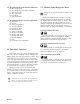
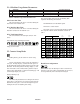
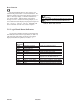
Reset Function
Pressing and holding this key will result in a reset
function being activated after a 5-second countdown. The
function is based on the current large display selection, see
table 12. The large display (1) will show countdown to
reset in this manner. When the button is pressed the
message CLr In 5 will show on the large display (1). At
one second intervals the display will progress through CLr
In 4, CLr In 3, CLr In 2, CLr In 1, and finally will
show CLEArEd when the reset action is complete.
0
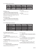
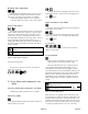
Reset while showing Output Count will reset all job
variables.
Reset while showing batch data will reset Number
of Batches and reload the Batch Down Count.
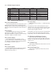
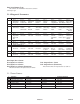
Reference Name Description
Designator
LED1 Tachometer Indicator Tracks the Tachometer input.
LED2 Not Used Turns on when MKE output is activated.
LED3 Suction Indicator Tracks the Suction output.
LED4 K1 Status of Relay K1
LED5 Pile Down Tracks the Pile down output.
LED6 Pile Up Tracks the Pile up output.
LED7 Pile Indicator Tracks the Pile outputs. If one of the Pile
outputs is on, this LED will be on.
LED8 Logic +5VDC Supply Shows status of Logic +5VDC Supply
LED9 Isolated +5VDC Supply Shows status of Isolated +5VDC Supply
LED10 Isolated +24VDC Supply Shows status of Isolated +24VDC Supply
LED11 Kicker Turns on when kicker output is activated.
Table 14. LED Status Indicators
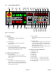
3.0 Logic Board Status Indicators
Several of the controller functions are monitored with
LED indicators located on the Logic Board (see Table 14).
The status of all other inputs are shown on the 8 Digit
display in Machine Setup mode (see Tables 1 - 6).
Table 13. Reset mode Selection