Manual Programming Software ProCam 1.10 for Absolute Switching Cam Encoders Baumer IVO GmbH & Co. KG Dauchinger Strasse 58-62 DE-78056 Villingen-Schwenningen Phone +49 (0)7720 942-0 Fax +49 (0)7720 942-900 info.de@baumerivo.com www.baumer.com 05.11 · 174.02.034/3 Subject to modification in technic and design. Errors and omissions excepted.
Content 1 Introduction 1.1 4 Product assignment 4 2 General Information 2.1 2.2 2.3 2.4 5 System requirements Installation Software version Information on commissioning 5 5 5 5 3 ProCam Program 6 3.1 Basics 3.2 Program procedure 3.2.1 Selecting encoder type 3.2.2 Encoder connected to PC - "Automatic selection" 3.2.3 Selecting encoder type from table - "Manual selection" 3.2.4 Starting encoder programming 4 Program Encoder 11 4.1 Menu and icon bar 4.1.1 File 4.1.2 Settings 4.1.3 Extras 4.1.
4.3.7 Speed monitoring 4.4 "Program encoder" programming mask 4.4.1 Edit cam program 4.4.2 Send cam program 4.4.3 Activate cam program 4.4.4 Dialog window 4.4.5 Program status 4.5 "Cam" programming mask 4.5.1 Program 4.5.2 Cam memory 4.5.3 Cam No. 4.5.4 Output 4.5.5 Name 4.5.6 ON/OFF 4.5.7 DTC ON/DTC OFF 4.5.8 Lock 4.5.9 Status 4.5.10 Name outputs 4.5.11 Enter DTC values 4.5.12 Lock outputs 4.6 "Display position" and "Activate cam program" mask 4.7 "Set position" mask 5 Connecting Encoder 34 5.
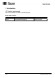
1 Introduction 1.1 Product assignment This ProCam software is suitable for the following types: Hollow shaft encoders Product Product Family interface RXA1H Cam-operated switchgroup RS232 or RS485 Manual_ProCam_V1-10_EN.doc 10.05.11 4/35 Baumer IVO GmbH & Co.
2 General Information 2.1 System requirements A PC with the operating system Windows 95/98/NT/2000/XP with one free RS232 serial port. An RS485/RS232 interface converter with automatic directional switchover is required for encoders with an RS485 interface. 2.2 Installation The installation is menu-guided. Please read the file "Readme.txt" on the included CD. Note: Under Windows NT/2000 and Windows XP, the installation can only be carried out with Administrator rights. 2.
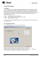
3 ProCam Program 3.1 Basics The ProCam program is a software for programming Baumer IVO cam encoders. It can be used to read out, change, program and display the encoder data. To make programming as simple as possible, the user can select only the fields valid for the respective state. Fields which cannot be selected in the current state have a gray background. Before the encoder can be programmed, the encoder type must be selected. This results in a logical procedure following the program start: 1. Step 2.
3.2.1 Selecting encoder type The encoder can be selected in the first step. The program offers automatic selection when an encoder is connected to the interface. If there is no connection to the encoder, a desired encoder type can be selected from the list with "Manual selection". Manual_ProCam_V1-10_EN.doc 10.05.11 7/35 Baumer IVO GmbH & Co.
3.2.2 Encoder connected to PC - "Automatic selection" Automatically detected encoder model With an encoder selected, the encoder type can be read out (Automatic selection). This information is necessary to provide the corresponding parameters for programming. If the encoder or the cable connection is not properly connected, an error message is displayed. If the automatically detected encoder does not match the encoder rating plate, please contact Baumer IVO. Manual_ProCam_V1-10_EN.doc 10.05.
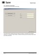
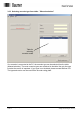
3.2.3 Selecting encoder type from table - "Manual selection" Table for selecting encoder model If no encoder is connected to the PC, the encoder type can be selected from the table (Manual selection). The most common types are contained in the table. Not only the type, but also the version is important. If your type is not included, please contact Baumer IVO. The type and version can be read off the encoder rating plate. Manual_ProCam_V1-10_EN.doc 10.05.11 9/35 Baumer IVO GmbH & Co.
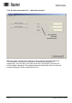
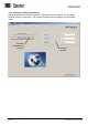
3.2.4 Starting encoder programming After successfully selecting the encoder, programming can be started. The "Program encoder" button is now active. The selected encoder is shown again in the right-hand mask. Encoder programming is active Manual_ProCam_V1-10_EN.doc 10.05.11 Selected encoder 10/35 Baumer IVO GmbH & Co.
4 Program Encoder The "Program encoder" mask now enables the programming of all parameters possible for this encoder. Resolution tab Outputs tab Program tab Dialog window The parameters for the encoder can be set with the tabs "Resolution", "Outputs" and "Program". The dialog window offers additional support and explanations for the selected window. Tab "Resolution" tab "Outputs" tab "Program" tab Manual_ProCam_V1-10_EN.doc 10.05.11 Explanations See Chapter 4.2 See Chapter 4.3 See Chapter 4.
4.1 Menu and icon bar 1 5 No. 1 2 3 4 5 6 2 6 Chapter 4.1.1 4.1.2 4.1.3 4.1.4 4.1.5 4.1.6 3 7 4 8 9 10 11 Buttons File Definitions Extras Info Reprogramming Open file No. 7 8 9 10 11 Chapter 4.1.7 4.1.8 4.1.9 4.1.10 4.1.11 Buttons Save file Print Load data from encoder Save data in encoder Display position 4.1.1 File In the "File" menu item the following items can be selected: New: A programming mask with the basic setting is loaded. Open: A saved program can be loaded.
4.1.2 Settings In the "Settings" menu item the COM 1 to COM 6 serial port to which the encoder is connected can be selected. In addition, the baud rate and the address of the encoder can be set. The other parameters such as Parity, Stop bits and Data bits can be checked here. The port parameters are permanently set for the RXA1H series. - Baud rate: 38400 - Parity: Even - Stop bits: 1 - Data bits: 8 Manual_ProCam_V1-10_EN.doc 10.05.11 13/35 Baumer IVO GmbH & Co.
4.1.3 Extras Read data: Send data: Display position: Set position: Reset: Encoder address: Set password: The data are requested from the connected encoder The current programming is saved in the encoder The "Display position" screen mask is opened (see Chapter 4.6) The mask for assigning a position value is opened (see Chapter 4.7) The encoder receives a reset command. The effect is identical to switching the supply voltage off and then on again. No cam programs or stored settings are deleted or changed.
4.1.4 Info With Info the version of the ProCam and encoder software can be displayed. 4.1.5 Reprogramming The display mask is reset to the basic setting. The same function can also be run with "File ⇒ New". 4.1.6 Open file Programming stored in the PC can be loaded. The same function can also be run with "File ⇒ Open". 4.1.7 Save file The current data are saved in the PC. The same function can also be run with "File ⇒ Save". 4.1.8 Print The current encoder data are printed out.
4.2 "Resolution" programming mask The resolution and other basic parameters of the encoder can be set with this programming mask. The picture below shows the maximum possible settings. However, only those parameters are shown which are supported by the selected encoder. 12 10 9 11 1 2 8 3 4 No. 1 2 3 4 5 6 Chapter 4.2.1 4.2.2 4.2.3 4.2.4 4.2.5 4.2.6 5 6 Field Code (steps) Counting direction Speed scaling Revolutions Steps/revolution Total range Manual_ProCam_V1-10_EN.doc 10.05.11 No.
4.2.1 Code (steps) The code (steps) is permanently set to binary. 4.2.2 Counting direction With the counting direction it is possible to choose between "increasing clockwise"and "decreasing clockwise". "Increasing clockwise" means that with clockwise rotation (looking from the front at the encoder shaft), the position values increase, and with "decreasing clockwise" these decrease accordingly. 4.2.
4.2.4 Revolutions With singleturn encoders, the value for the rotations cannot be set. It is always set to 1. 4.2.5 Steps/revolutions Number of steps with which a rotation of the encoder axis is to be resolved. The possible value range lies between 2 and 8192 steps/rotation. 4.2.6 Total resolution The total resolution is the product of steps/rotation multiplied by the number of rotations. Calculation formula for the total resolution: 1. Singleturn encoder 1 X Steps/revolutions = Total Resolution 2.
4.2.10 Read encoder data The connected encoder is read out. Before the tabs "Resolution", "Outputs" and "Program" are overwritten, they can be saved. If the connected encoder type does not match the one selected, the following error message appears: If the set encoder and connected encoder types are identical, the data are read in and displayed. 4.2.11 Send encoder data The encoder connected to the interface is programmed with the set parameters.
4.3 "Outputs" programming mask Each of the 16 outputs can either switch cams or assume a special task as a special output. This window controls the properties of each individual output. Each special function carried out (No. 2 - 5) can be assigned to exactly one output. On the other hand, the property "Inverted" (No. 6) can be assigned to any output, regardless of whether it is defined as a cam output or as a special output. 1 2 3 4 5 6 7 No. 1 2 3 4 5 6 7 Chapter 4.3.1 4.3.2 4.3.3 4.3.4 4.3.5 4.3.
4.3.1 Output The outputs are marked No.1 to No.16. This numbering cannot be changed. However, each output can be assigned an additional plain text designation (see Section 4.6.10) 4.3.2 Data Valid The output is assigned the special function "Data Valid". It becomes active when the continuous internal self-monitoring function of the encoder has detected a problem, e.g. an overloading of the output driver or an impermissible position value.
4.4 "Program encoder" programming mask The programmable cam-operated switchgroup permits the execution of switching processes. Here a total of 1,024 cam switching points distributed over a maximum of 16 cam programs can be set. Each of the 1,024 cams can be assigned to one of the 16 switching outputs. After the "Program encoder" tab is selected, the following window appears: 1 4 5 2 3 No. 1 2 3 4 5 Chapter 4.4.1 4.4.2 4.4.3 4.4.4 4.4.5 Manual_ProCam_V1-10_EN.doc 10.05.
4.4.1 Edit cam program Create: Clicking on the "Create" button starts the entry of a new cam program in ProCam. In the process, the next free program number is automatically assigned. Then the program name and the number of cams can be entered. "Continue" opens the "Edit cam program" mask (see Chapter 4.5). Change: By clicking the "Change" button, the data of the selected cam program can be changed. Clicking on "OK" opens the "Change cam program" window.
Copy: Clicking on the "Copy" button copies the data of the selected cam program to a new cam program to be selected in ProCam. The program automatically suggests the next free Program No., whereby a free Program No. and a new program name can also be assigned. Information: It is not possible to overwrite an existing cam program. . Delete: By clicking on the "Delete" button, the data of the selected cam program can be deleted in ProCam. Manual_ProCam_V1-10_EN.doc 10.05.11 24/35 Baumer IVO GmbH & Co.
Save file: The current data are saved in the PC. The same function can also be run with "File ⇒ Save". Open file: Programming stored in the PC can be loaded. The same function can also be run with "File ⇒ Open". 4.4.2 Send cam program Send data The current programming is saved in the encoder. The same function can also be run with "Extras ⇒ Send data". Request data The data are requested from the connected encoder. The same function can also be run with "Extras ⇒ Data". 4.4.
4.5 "Cam" programming mask After selection the following window appears: 2 1 3 4 10 No. 1 2 3 4 5 6 Chapter 4.5.1 4.5.2 4.5.3 4.5.4 4.5.5 4.5.6 Buttons Program Cam memory Cam No. Output Name ON/OFF 5 6 7 11 8 9 12 No. 7 8 9 10 11 12 Chapter 4.5.7 4.5.8 4.5.9 4.5.10 4.5.11 4.5.12 Buttons DTC ON/DTC OFF Lock Status Name outputs Enter DTC values Lock outputs Context messages appear on the mouse pointer which refer to the respective permissible value range in the table column.
4.5.2 Cam memory The "Cam memory" display shows how many of the total number of available cams have already been used for switching processes (in the picture 30 of 1,024). 4.5.3 Cam No. The cam number is permanently specified in each case and cannot be changed. 4.5.4 Output Enter the number of the output this cam is to act on here. The value range is 1 - 16. If you enter a "0", the cam remains inactive. 4.5.
4.5.9 Status Input parameters for status: 0 = Default cam bidir (bidirectional, acting in both rotating directions) 1 = Time cam bidir (bidirectional, acting in both rotating directions) 2 = Default cam pos (only acting in the positive rotating direction) 3 = Default cam neg (only acting in the negative rotating direction) 4 = Time cam pos (only acting in the positive rotating direction) 5 = Time cam neg (only acting in the negative rotating direction) 4.5.
4.5.11 Enter DTC values Compensation times can be entered here to compensate delay times with connected devices and processes. Regardless of the current speed, the outputs are switched earlier by the entered time. The time unit in this window is milliseconds, and up to 1,000 ms are possible. The entry is made separately for each output, i.e. always "path-by-path". In addition, different values can be specified for the switch-on and switch-off time. 4.5.
4.6 "Display position" and "Activate cam program" mask The display module can display the position and the special outputs of the connected encoder. This can be selected under "Extras ⇒ Display position". After the display module starts, the following mask appears. 1 3 7 2 4 6 5 No.
Start cam program Clicking on the "Start" button starts the selected program. All outputs programmed as cam outputs assume the state corresponding to the cam position. Time cams are treated as "Time expired" during the program start. Direction cams are set during the program start with the encoder stopped as if the encoder had last run in the positive direction. Positive is the rotating direction in which the position values increase. (See Chapter 4.2.2 "Counting direction" for setting).
4.7 "Set position" mask With this function the cam encoder is assigned a position value ("Preset value"). In the simplest case, the encoder could be set to "0000" in this way to calibrate the mechanical zero position of the shaft with the display "0000". However, any other position value within the set encoder resolution can also be transferred here. To check this, the current position shown continually updated at the top of the window.
Before assigning a position value, the encoder rotating direction (positive in clockwise direction or opposite) must be specified and programmed in the encoder. This information is transmitted to the encoder together with cam tables and other data as part of the "Send data" function. The "Send data" function should therefore be carried out once with the final rotating direction before the encoder is assigned a position value. The assignment of a position value may lead to a considerable position jump.
5 Connecting Encoder 5.1 Connection between PC and encoder To realize the simplest possible connection to the PC, the encoder is equipped with an RS232 interface. With this the encoder can be connected directly to the PC. If the transfer distance is greater than 30 m, it is advisable to use the RS485 interface. In this case an interface converter with an automatic directional switchover function is required on the PC (not included in the delivery scope). 5.1.
6 Index Installation · 5 A Automatic selection · 8 R M Manual selection · 9 B Back to main menu · 12 C Code (steps) · 17 D Decreasing clockwise · 17 Display module · 30 I N Request data · 14 Reset · 14 RS232 · 34 RXD · 34 New · 12 S O Save · 12 Save as · 12 Send data · 14 Steps · 18 Open · 12 Operating system · 5 T P Print · 12 Print setup · 12 Programming mask · 16 Tabs · 11 Total resolution · 18 TxD · 34 Increasing clockwise · 17 Manual_ProCam_V1-10_EN.doc 10.05.