
Instruction Manual

www.baumer.com
Operators instructions: 11112759 Page 2 / 8
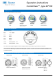
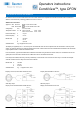
Display mode
There are 9 different display modes available
Digital Analogue Bar graph Tank
small analogue horizontal tank illustration
large same w. bar graph vertical bottle illustration
same w. value
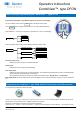
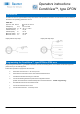
Electrical connection
Pin 1 + 4…20 mA
Pin 2 - 4…20 mA
Pin 3 Relay 1
Pin 4 Relay 1
Pin 5 Relay 2
Pin 6 Relay 2
Com 1 FlexProgrammer ① red
Com 2 FlexProgrammer ① black
Pin 3 and 5 can be jumpered together if common supply is used for the two relays, e.g. via a M12 5-pin connector.
When instruments like PFMx are delivered with DFON display terminal 1 and 2 are not connected. In this case the DFON is pow-
ered and will have data through a special ribbon cable (UnitCom). When connected via UnitCom the DFON and transmitter can be
programmed together.
UnitCom
Electrical connection
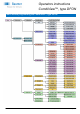
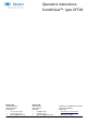
Dimensions for mounting of stand alone instrument
Operators instructions
CombiView™, type DFON
Wall mounting Panel mounting Tube mounting
PCD for holes: Ø95 mm Panel cut out: 80 mm Tube diameter: Ø38 mm
PCD for holes: 82 mm Ø51 mm
Ø64 mm