
Owner manual


User manual Scatec-10 / -15 36 / 44 Baumer Electric AG
Version 2011-03 www.baumer.com Frauenfeld, Switzerland
Version 2
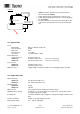
• Scatec housing is grounded (use teeth lock washers
when mounting the Sactec)
• Cable shield properly grounded at the controller end
• Cable shield properly attached to the connector plugging
into the Scatec.
• Keep the impedance of the interconnection between the
control unit’s ground and the Scatec ground sufficiently
low.
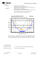
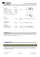
11.7 Optical data
Laser
Wavelength 650 nm - 680 nm (visible red)
Pulse frequency 50 kHz
Duty cycle 50%
Average power < 1.0 mW
Laser class 2 (to IEC 60825-1 / 2007)
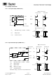
Beam dimensions
at emission point about 2.5 x 4.0 mm
Scatec-10: 70 mm beneath sensor Line focus, 6 mm long
Scatec-15: 100 mm beneath sensor Line focus, 8 mm long
Focus position
Scatec-10: 70 mm beneath sensor
Scatec-15: 100 mm beneath sensor
Optical receiver equipped with near infrared suppression and daylight suppression filter
11.8 Application data
Measuring range
Scatec-10: 0 to 90 mm beneath sensor
Scatec-15: 0 to 120 mm beneath sensor
Mounting height
Scatec-10: 70 mm
Scatec-15: 100 mm
Object speed 2 m/s maximum (5 m/s maximum for thicker edges)
Minimum object spacing 10 mm @ v = 1 m/s and output pulse length 10 ms, or proportional to the
speed and output pulse length
Counting rate 1.5 million maximum copies/h (@ 2 ms output pulse length and 0 ms dead
time)
Product orientation Folded or cut edge facing laser beam
Output pulse length 0.2 … 100 ms adjustable
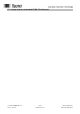
Scatec-1x
Control unit
Main connector
Low-impedance
interconnection