
Owner manual


User manual Scatec-10 / -15 35 / 44 Baumer Electric AG
Version 2011-03 www.baumer.com Frauenfeld, Switzerland
11.5 Synchronization input
• opto-isolated input
• input signals between 5V and 30 V
• for NPN- or PNP-open collector, push-pull, or TTL encoder output
• Scatec FLDM 170G…… (push-pull output) accepts an A/B-channel encoder
• Scatec FLDM 170C…… (opto-isolated output) accepts an A-channel encoder only.
• synchronization input signal levels logical high: > 3.8 V (> 2.2 mA)
logical low: < 1.8 V (< 0.7 mA)
• frequency max. 50 kHz
• reverse polarity: protected
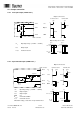
11.6 Wiring instructions
In order to achieve optimum protection of the Scatec against electromagnetic interference
• use shielded cables
• keep the ground impedance sufficiently low
We suggest the following two grounding schemes:
Version 1
• Scatec housing is grounded (use teeth lock washers when
mounting the Sactec).
• Cable shield not grounded at the controller end.
• Cable shield properly attached to the connector plugging
into the Scatec.
Pin 5
( Pin 2 )
Scatec
Pin 4
Pin 2
(FLDM 170G...
only! )
positive
negative
positive
Pin 4
Pin 5
( Pin 2 )
Pin 4
+ V
E
+ V
E
Pin 5
( Pin 2 )
Pin 4
+ V
E
Pin 5
GND
E
GND
E
GND
E
Pin 5
( Pin 2 )
Pin 4
+ V
E
GND
E
NPN open
collector
PNP open
collector
Push-pull
TTL
Scatec-10/ -15
Main connector
+ V
E
: Output voltage of the encoder
GND
E
:
GND of the encoder
Scatec-10/-15
Main connector
Scatec-10/-15
Main connector
Scatec-10/-15
Main connector
Scatec-10/-15
Main connector
Scatec-1x
Controller
Main connector