
User Manual


en_BA_U500_UR18_Gen2_IO-Link.docx 9/43 Baumer Electric AG
04.04.2019/ Frauenfeld, Switzerland
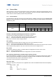
Bit 16 to 47: MDC
MDC stands for measurement data channel. Via this channel the distance value or the switch counts of SSC1,
2 or 4 can be read out as 32 bit integer value. See section 4.2 to learn how to configure the MDC.
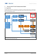
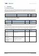
3.2.2 Process Data-Out
This data is cyclically sent from the master to the sensor (MasterSensor).
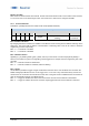
IO-Link Process Data Output
Bit:
7
6
5
4
3
2
1
0
Trigger
Find Me (Localization: LEDs
flashing)
Disable
Transducer
Bit 0: Disable Transducer
By changing this bit the transducer is disabled. This switches off the sensing element without switching off the
electronics. The sensor will not deliver a measurement or switching value. This can be useful to measure
neighbouring sensors sequentially.
Bit 0 = 0 → Transducer is enabled
Bit 0 = 1 → Transducer is disabled
Bit 1: Find Me Function
Signalling e.g. by flashing LEDs (green, yellow, and red) on the sensor to locate and physically identify a
sensor in a machine or system. The signalling can be triggered, for example, from the engineering tool of the
controller.
Bit 1 = 0 → Find Me Function is deactivated
Bit 1 = 1 → Find Me Funktion is activated, LEDs are flashing.
Bit 2: Trigger
Via this Bit it is possible to trigger a single measurement from the sensor. For this Bit to have a function the
DI/DO Settings.Input Mode has to be set to Trigger see 4.7.3.4. This is very useful when many sensors are
mounted next to one another and do influence each other. Using this mode no additional wires are needed in
order to sequentially measure on multiple sensors.
Bit 2 = 0 → Trigger is disabled, the sensor does not measure and the sensor element is deactivated
Bit 2 = 1 → Trigger is enabled, the sensor measures edge-triggered and the sensor element is activated.