
User Manual


en_BA_U500_UR18_Gen2_IO-Link.docx 8/43 Baumer Electric AG
04.04.2019/ Frauenfeld, Switzerland
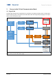
3.2 Process Data
With the sensor in the IO-Link communication mode, process data is cyclically exchanged between the IO-
Link master and the device. Process data is exchanged to and from the sensor (SensorMaster). The
master does not need to explicitly request these process data.
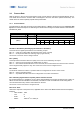
3.2.1 Process Data-In
Process Data-In is sent from the sensor to the master (Sensor Master). As shown in Figure 4 Process data
Input, the Process Data Input is an 48bit string and structured according to the Smart Sensor Profile definition
PDI48.INT32_INT8.
IO-Link Process Data Input
47 16
15 8
7 0
IntegerT(32)
IntegerT (8)
8 bit
Measurement value
(MDC)
Scale
Baumer specific
7
6
5
4
3
2
1
0
SSC4
Alarm
Quality
SSC2
SSC1
Figure 4 Process data Input
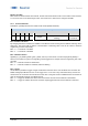
Bit 0/Bit 1: SSC1/SSC2 (Switching Signal Channel 1 & Channel 2)
These bits are the digital representation of the switching outputs.
Bit1 = 0 → There is no object within the switching range (Logic: Normal)
Bit1 = 1 → An object lies within the switching range (Logic: Normal)
See section 4.3 to learn how to configure this bit
Bit 2: Quality
This bit provides information about the quality of the sonic echo reflected by the object.
Bit2 = 0 → Sensor has enough signal to reliable detec an object
Bit2 = 1 → The reflection detected from the sensor is critical, it is recommended to check sensor in the machine.
Sensor might be badly aligned or dirty. See section 4.5 to learn how to configure this bit.
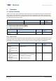
Bit 3: Alarm
The alarm bit indicates that there is a problem with the configuration or function of the sensor.
Bit3 = 0 → Sensor operates properly.
Bit3 = 1 → A problem with either the sensor configuration or function was detected.
Bit 5: Switching Signal Channel 4 (SSC4), Switch Counter Function
By configuring SSC4, it is possible to set up a binary signal related to the number of switchcounts of SSC1 or
SSC2. An auto-reset and timefilters are included, to be able to create a full-featured counter being able to
count lot sizes without any need to code software on the PLC.
See section 4.3.4 to learn how to configure this bit.
Bit 8 to 15: Scale
Value is the exponent to the power of ten, applicable to the value of the Measurement Data Channel (MDC)
Example:
- Value of MDC 1000
- Unit m
- Scale -6
- Means 1000*10
-6
m or 1000 m