
User Manual

en_BA_U500_UR18_Gen2_IO-Link.docx 36/43 Baumer Electric AG
04.04.2019/ Frauenfeld, Switzerland
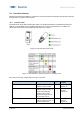
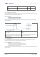
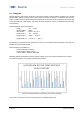
Figure 30: Window Teach, switching behavior
Figure 30 shows the switching behavior of the selected SSC if the teach-in was successful.
In this example, the hysteresis is configured to be right aligned (See 4.3.2.4 for more details regarding
hysteresis alignment)
Which SP was teached at a higher distance does not have any influence on the switching behavior
(SP1<SP2, SP1>SP2).
5.3 Static Analog out
For sensors with an analog output (.D types), the distance range mapped to the analog output range can be
modified (reduced and/or inverted). Aside from the teach-by-value approach described in section 4.7.2.2,
also a teach by command approach is possible.
Command sequence:
- Place object at the position which should be teached for the lower analog output value, position (A)
- Execute Teach Analog Output Min
- Place object at the position which should be teached for the upper analog output value, position (B)
- Execute Teach Analog Output Max
- Execute Teach Apply to store the value
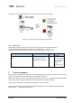
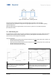
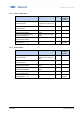
Figure 31 Reduced range of the analog output
value for improved accuracy (analog value
increased with distance)
Figure 32 Reduced and inverted range of the
analog output value for improved accuracy and
different slope (analog value decreases with
distance)