
User Manual

en_BA_U500_UR18_Gen2_IO-Link.docx 31/43 Baumer Electric AG
04.04.2019/ Frauenfeld, Switzerland
4.8 Local User Interface
Different parameters are available to configure the local user interface which means the indication LEDs and
the local-teach-in (qTeach, teach by wire)
4.8.1 Indication LEDs
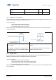
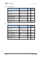
Figure 26 shows which LED indicates which status. The relationship between mode/switching output and
LED can not be modified, but it is possible to deactivate or to invert the LED behaviour. In addition, the
yellow LED continuously works as alignment aid only for the .R types.
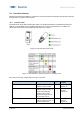
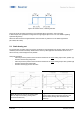
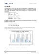
Figure 25: LED Indication U500, UR18
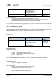
Figure 26: LED Indication - Standard-behavior in operating mode
Note: Only sensors with 2 digital outputs do have a red LED.
Parameter name
Short Description
Rights
Unit / Allowed
values
LED Settings.Green.Mode
Switches the LED off, no
change of other function
rw
On / Off
Default: On
LED Settings.Yellow.Mode
Switches the LED off, no
change of other function, or
inverts the relationship
between LED and pin
Inverted:Pin high, LED off
On: Pin high, LED on
rw
On / Off /
Inverted
Default: On
LED Settings.Red.Mode
Switches the LED off, no
change of other function, or
inverts the behaviour
rw
On / Off /
Inverted
Default: On