
User Manual

en_BA_U500_UR18_Gen2_IO-Link.docx 29/43 Baumer Electric AG
04.04.2019/ Frauenfeld, Switzerland
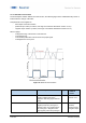
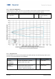
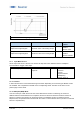
Figure 24 Reduced sensing range for improved accuracy
Parameter name
Short Description
Rights
Unit / Allowed
values
Analog
Output.Distance@AnalogMin
Set the distance value in mm at the
minimum value of the Analog Output
rw
Limit A0: 50 to
1500mm
Default: 70mm
Analog
Output.Distance@AnalogMax
Set the distance value in mm at the
maximum value of the Analog Output
rw
Limit A0: 50 to
1500mm
Default: 1000mm
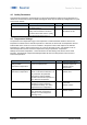
4.7.3 Input Mode of Pin 5
Via the input mode of Pin 5 the user can choose via drop-down menu between Teach-in / Multiplex /
Synchronization / Trigger / None Input.
Parameter name
Short Description
Rights
Unit / Allowed values
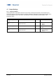
DI/DO Settings.Input Mode
Select the function of the
Input Pin
rw
-None
-Teach-In
-Trigger
-Synchronisation
-Multiplexing
Default: Teach-In
4.7.3.1 Teach-in
In this mode the sensor can be teached through wire teach. Depending on the sensor type different modes
are available. This is explained in the MAL of the corresponding article. The MAL can be found on the
product page of each article.
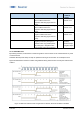
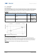
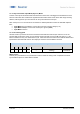
4.7.3.2 Multiplex (MUX) Mode
Link the control pin of both sensors to each other. While the first sensor is measuring, the second is
disabled. After the first measurement is completed, the second sensor is allowed to send and receive its
signals. In maximum ten sensors can be interconnected. The multiplex function increases the sensor
response time, the specified value increases with the number of connected the sensor (number of connected
sensors x response time).