
User Manual

en_BA_U500_UR18_Gen2_IO-Link.docx 18/43 Baumer Electric AG
04.04.2019/ Frauenfeld, Switzerland
Parameter name
Short Description
Rights
Unit / Allowed values
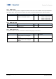
Reflector Tolerance
Set reflector tolerance as
percentage of the sensing range
rw
Limit: 1…20%
Default: 5%
4.3.3 Timefilter
This changes the timing of the switching signals, for example to avoid bouncing/suppress false switching
operation. The ability to directly parametrize and configure the timing on the sensor itself, removes the need
to have additional coding on the PLC or to use pulse stretching adapters.
The described time filters can be configured and applied to each SSC individually.
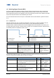
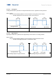
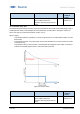
4.3.3.1 Response Delay Time
The response delay time defines the time, the measurement value needs to be above (single point mode) or
inside (window mode) the switchpoints of the related SSC until its status changes to active (or inactive, if the
logic is inverted as described in section 4.3.2.1)
When to apply?
- To avoid the detection of small peaks/false switching operations due to structure changes of the
background or similar.
- To avoid wrong switching of known disturbances such as the wheel of a mixer
- To avoid bouncing.
- To optimize the timing of the execution of a subsequent actor triggered by the output of the sensor.
Figure 19: Response Delay