
User Manual


en_BA_U500_UR18_Gen2_IO-Link.docx 17/43 Baumer Electric AG
04.04.2019/ Frauenfeld, Switzerland
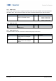
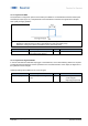
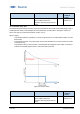
4.3.2.4.3 Center Aligned
A compromise between left and right aligned. The hysteresis is aligned symmetrical around the individual
setpoints.
Figure 16 Center Aligned, Single Point Mode
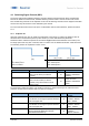
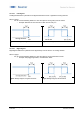
Figure 17 Center Aligned, Window Mode
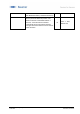
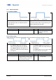
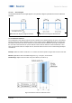
4.3.2.5 Reflector Tolerance
The configuration of the reflector tolerance is only relevant for the reflective barrier (.R types). The reflector
tolerance states the relative allowable variance of the reflector position. Figure 18 shows an example with
two different tolerances that can be selected. The two shown reflector tolerances (A and B) correspond to
the ones who can be teached via q-teach. With IO-Link the reflector tolerance can be set between 1 and
20%. An object that enters for example area A, will not be detected as the sensor cannot distinguish object
and reflector.
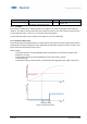
Example: Reflector Position of 500 mm ± 5 % means the reflector position ranges from 475 mm to 525 mm.
Benefit: Applications with an unstable background, e.g. conveyors, can be solved.
Disadvantage: Object must be further away from reflector (at least 10 %).
Figure 18: Reflector tolerance reflective barrier