
User Manual

en_BA_U500_UR18_Gen2_IO-Link.docx 14/43 Baumer Electric AG
04.04.2019/ Frauenfeld, Switzerland
4.3.2 SSC Configuration
4.3.2.1 Switching Mode
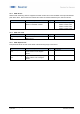
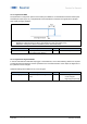
Figure 7 Single point
A single switchpoint (SP1) is defined at which the
sensor switches.
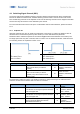
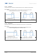
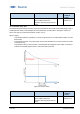
Figure 8 Window Mode
The sensor switches within a range defined by two
different setpoints (SP1 and SP2)
Parameter name
Short Description
Rights
Unit / Allowed values
SSC1 Config.Mode
Selects the SSC switch mode
rw
-Disabled
-Single Point (Default)
-Window
4.3.2.2 Channel Logic
Allows to change the output logic from Normally Open (NO, Normal) to Normally closed (NC, Inverted).
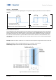
Single Point Mode Window Mode
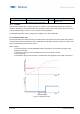
Single Point Mode Window Mode
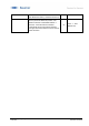
Figure 9 «Normal» or NO setting
- The output is high, when the object is
within the range defined by the setpoints.
- The output is low when the object is not
present our outside of the range defined by
the setpoints
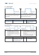
Figure 10 «Inverted» or NC setting
- The output is high when the object is not
present our outside of the range defined by
the setpoints
- the output is low, when the object is within
the range defined by the setpoints
Parameter name
Short Description
Rights
Unit / Allowed values
SSC1 Config.Logic
Selects the SSC logic. It can be
changed between "active if object
is present (normal)" or "inactive if
object is present (inverted)"
rw
- Normal (NO) (Default)
- Inverted (NC)