Instruction Manual Ultrasonic Sensor Family U500 and UR18 with IO-Link
Instruction Manual for Ultrasonic Sensor Family U500 & UR18 with IO-Link Content 1 Sensors covered by this manual ................................................................................................ 4 2 2.1 2.2 2.2.1 2.2.2 2.3 2.4 2.5 IO-Link Introduction ..................................................................................................................... 4 SIO / Di Mode Mode ......................................................................................................
5.2.1 5.2.2 5.3 Single Point / 1-Point Teach ......................................................................................................... 35 Window Teach .............................................................................................................................. 35 Static Analog out ........................................................................................................................... 36 6 6.1 6.2 6.3 6.4 6.5 6.6 6.6.1 6.6.2 6.6.3 Diagnosis .............
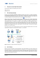
1 Sensors covered by this manual These instruction apply to the following sensor versions: U500.xyz.2-XXX UR18.xyz.2-XXX 2 IO-Link Introduction IO-Link is an IO technology standardized worldwide according to IEC 61131-9. It permits manufacturerindependent digital, bidirectional point-to-point communication. For this purpose, sensors are connected to the IO-Link master via standardized 3-wire plug-in cables.
2.2 IO-Link Communication Mode The IO link communication mode is initiated by the master (PLC) with a standardized command sequence, this sequence is called “wake-up”. After successful completion of the wake-up sequence the IO link communication starts. Data is the most important basis for process and product optimization. With the help of IO-Link, valuable additional data can be made accessible. Sensor and Master can exchange two different types of data (cyclic and acyclic data).
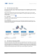
2.4 Off-Line Parametrization Off-line sensor parameter adjustment via convenient user interfaces in the PC (via USB Master) or via Wireless App (via Wireless Master). Sensors can be conveniently configured at the desk and installed without further teach-in. Even if IO-Link is not implemented in the machine control, sensors can be operated in SIO mode and use this advantage 2.
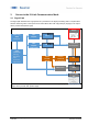
3 Sensor in the IO-Link Communication Mode 3.1 Signal Path The signal path describes the rough position of a parameter in the signal processing chain. The path starts with the measuring value in the top left corner and finishes either with a physical pin (top right) or as output via the process data (bottom right).
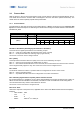
Process Data 3.2 With the sensor in the IO-Link communication mode, process data is cyclically exchanged between the IOLink master and the device. Process data is exchanged to and from the sensor (SensorMaster). The master does not need to explicitly request these process data. 3.2.1 Process Data-In Process Data-In is sent from the sensor to the master (Sensor Master).
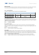
Bit 16 to 47: MDC MDC stands for measurement data channel. Via this channel the distance value or the switch counts of SSC1, 2 or 4 can be read out as 32 bit integer value. See section 4.2 to learn how to configure the MDC. 3.2.2 Process Data-Out This data is cyclically sent from the master to the sensor (MasterSensor).
4 Parameter System Commands 4.1 A factory reset of the sensor activates the default parameters as programmed in the factory. All parameters changed by the user will be lost. The factory reset can also be triggered via local teach-in (qTeach or wire teach) directly at the sensor (see assembly instruction for more information) where only the parameters that are changed via teach-in will be reset.
4.2.3 MDC Source Selects which measuring value is mapped to the MDC channel and is then available via the process data-IN path. When SSC1, SSC2 or SSC4 is selected the number of switches detected by the channel is shown. Parameter name MDC Selection.Source 4.2.
4.3 Switching Signal Channel (SSC) The sensor features three different switching channels. Switching Signal Channels SSC1 and SSC2 are reserved for distance measurements, whereas Switching Channel 4 has a counter function with an autoreset. All switching channels can be adjusted via IO-Link. All switching channels can be mapped to the MDC as well. Then they will show the counts detected by the channel.
Reflector.Tolerance ReflectorTolerance; SP2=ReflectorPosition*(1+ReflectorTolerance) Select the reflector tolerance, works together with the parameter Reflector position. The reflector tolerance is selectable between 1 and 20 %. It sets the tolerance window symmetrically around the reflector position. The upper and lower tolerance can be read off at SP1 and SP2. en_BA_U500_UR18_Gen2_IO-Link.docx 04.04.
4.3.2 SSC Configuration 4.3.2.1 Switching Mode Figure 7 Single point Figure 8 Window Mode A single switchpoint (SP1) is defined at which the sensor switches. The sensor switches within a range defined by two different setpoints (SP1 and SP2) Parameter name SSC1 Config.Mode Short Description Selects the SSC switch mode Rights rw Unit / Allowed values -Disabled -Single Point (Default) -Window 4.3.2.
4.3.2.3 Hysteresis Width The hysteresis is configured in percent of the switch point distance. It is the difference between switch point and reset point (see Figure 11). This parameter can be beneficial to smoothen out signals when samples have quickly changing positions.
4.3.2.4.1 Left Aligned Left Aligned defines the hysteresis to be aligned towards the sensor / against the sensing direction. When to apply? - For an accurate switching distance in case the object is moving away from the sensor o Example: Detection of the low level of a tank to avoid a dry-run Figure 12 Left Aligned, Single Point Mode 4.3.2.4.2 Figure 13 Left Aligned, Window Mode Right Aligned Right Aligned defines the hysteresis to be aligned away from the sensor / in sensing direction.
4.3.2.4.3 Center Aligned A compromise between left and right aligned. The hysteresis is aligned symmetrical around the individual setpoints. Figure 16 Center Aligned, Single Point Mode Figure 17 Center Aligned, Window Mode 4.3.2.5 Reflector Tolerance The configuration of the reflector tolerance is only relevant for the reflective barrier (.R types). The reflector tolerance states the relative allowable variance of the reflector position.
Parameter name Reflector Tolerance Short Description Set reflector tolerance as percentage of the sensing range Rights rw Unit / Allowed values Limit: 1…20% Default: 5% 4.3.3 Timefilter This changes the timing of the switching signals, for example to avoid bouncing/suppress false switching operation. The ability to directly parametrize and configure the timing on the sensor itself, removes the need to have additional coding on the PLC or to use pulse stretching adapters.
Parameter name Short Description Rights Response Delay.SSC1 Time Sets / indicates the response delay time in milliseconds for the respective switching signal channel (SSC). rw Unit / Allowed values 0 to 60.000 ms Default: 0 ms 4.3.3.
en_BA_U500_UR18_Gen2_IO-Link.docx 04.04.
4.3.3.3 Minimal Pulse Duration The minimal pulse duration defines the minimum time, the switching signal of the related SSC stays active or inactive after the change of its status. This parameter can be applied on - both slopes / active and inactive - positive slope / active (or inactive, if the logic is inverted as described in section 4.3.2.1) - negative slope / inactive (or active, if the logic is inverted as described in section 4.3.2.
4.3.4 Counter / SSC4 For each individual SSC a switching counter is implemented, which can be used as diagnosis data or also as measurement value. The number of counts of each channel can also be mapped to the measurement data channel MDC by adjusting the MDC source (See section 0). Trigger of counter is on positive slope of related SSC. By configuring SSC4, it is also possible to set up a binary signal related to the number of switchcounts of SSC1 or SSC2.
Parameter name Short Description Rights Release Delay.SSC4 Time Sets / indicates the release delay time in milliseconds for the respective switching signal channel (SSC). Sets / indicates the response delay time in milliseconds for the respective switching signal channel (SSC). Sets / indicates the minimal pulse length in milliseconds for the respective switching signal channel (SSC).
4.4 4.4.1 Signal Processing Moving Average Filter This parameter is valuable for more experienced users or to fine tune the trade-off between accuracy and measurement speed. A reduced accuracy can be caused by weak reflecting objects, by fast temperature variations of the environment or wind disturbances. The negative results of these effects can be reduced with the moving average filter. As the moving average filter averages multiple values, it leads to an increased response time.
4.4.2 Sonic Cone Adjustment Via this parameter the width of the sonic cone is modified. This is useful to measure reflections from weak reflections objects (setting “wide”) or to measure through narrow openings (setting “narrow”). Parameter name Short Description Rights Unit / Allowed values Beam Forming.Sonic Set the width of the sonic cone rw - narrow Cone Adjustment - medium (Default) - wide Figure 2: Sonic cone Input Mode adjustment 4.4.
4.5 Quality Parameters This parameter indicates the signal strength from the received reflection relative to the set threshold. It is useful to be monitored by the PLC to detect weak signals which may be caused by misalginement or by dirt on the sensor surface. Parameter name Short Description Rights Unit / Allowed values units dB Quality.Value Quality value indicates the quality of ro the reflected signal Quality Bit.
4.7 4.7.1 Output Settings Switching Output Via this parameter it is possible to select the ouput circuit of the physical outputs. If set to PushPull, the circuit type (change from NPN to PNP) can also be modified by changing the external load according to the connection diagram, this can be found in the datasheet or in the Assembly Instruction (MAL) of the resepective article. Parameter name DI/DO Settings.OUT1 Circuit DI/DO Settings.
4.7.2 Analog Output 4.7.2.1 Output Scale Allows to change the upper and lower values of the analog output range. For example: the default range is 0 to 10 V, this can be modified to 2 to 8V. In terms of distance values mapped to analog values the modification would mean that the default mapping of 0V=70mm and 10 V=1000 mm, is modified to 2V = 70mm and 8V=1000 mm. When to use: When the master requires a different voltage or current range. Parameter name Short Description Rights Analog Output.
Figure 24 Reduced sensing range for improved accuracy Parameter name Short Description Rights Analog Output.Distance@AnalogMin Set the distance value in mm at the minimum value of the Analog Output rw Analog Output.Distance@AnalogMax Set the distance value in mm at the maximum value of the Analog Output rw 4.7.
4.7.3.3 Synchronization Input Mode (Sync-In.) Mode Link the control pin of all sensors within a limited area to each other. This triggers the measurement of all sensors at the same time. Interference signals which arrive later at the sensor due to their longer sensing distance, will be ignored. Up to ten sensors can be synchronized via control pin.
4.8 Local User Interface Different parameters are available to configure the local user interface which means the indication LEDs and the local-teach-in (qTeach, teach by wire) 4.8.1 Indication LEDs Figure 26 shows which LED indicates which status. The relationship between mode/switching output and LED can not be modified, but it is possible to deactivate or to invert the LED behaviour. In addition, the yellow LED continuously works as alignment aid only for the .R types.
LED Settings.Blue.Mode between output switching behaviour and pin Inverted:Pin high, LED off On: Pin high, LED on Switches the LED off, no change of other function rw On / Off Default: On If the LED mode is set - On, the behaviour of the related LED is as described in Figure 26. - Off, the LED is deactived except if the function Find Me is activated. (See section 3.2.2) - Inverted, the LED behaviour is inverted to the definition in Figure 26.
See Figure 27 for a graphical illustration of the teach-in procedure by using qTeach. Figure 27: Teach-In procedure Xpress by using qTeach 4.8.3 qTeach Lock By default the qTeach is locked 5 min after power up to avoid any undesirable manipulation. This lock timeout can be deactivated completely or adjusted from 1 … 120 min. Only the qTeach is being affected. Teach-in by wire is always possible, it does not lock.. 5 Parameter name Short Description Rights Teach Lock Settings.
5.1 Teach Channel Selection & Teach Status The described teach commands can be applied to individual switching signal channels. Before proceeding with the teach-in procedure, make sure to select the SSC that should be addressed. Furthermore different information are available to indicate the current mode and teach-in state of the selected switching signal channel to help to execute the right commands described in section 5.2 and 5.3.
System Command (Teach Apply) System Command (Teach Cancel) 5.2.1 wo wo Single Point / 1-Point Teach If the selected SSC is configured as Single Point mode ( Changing the mode is explained in section 4.3.2.
Figure 30: Window Teach, switching behavior Figure 30 shows the switching behavior of the selected SSC if the teach-in was successful. In this example, the hysteresis is configured to be right aligned (See 4.3.2.4 for more details regarding hysteresis alignment) Which SP was teached at a higher distance does not have any influence on the switching behavior (SP1SP2). 5.3 Static Analog out For sensors with an analog output (.
Parameter name Output Scale Distance at Analog Min Output Scale Distance at Analog Max 6 Short Description Teach-in the distance, mapped to the lower analog output value Teach-in the distance, mapped to the upper analog output value Rights wo wo Diagnosis In addition to solving the primary application, the simple evaluation of secondary data, such as temperature, supply voltage or operating time, allows for predictive maintenance and thus optimum machine availability. 6.
Device Temperature.
6.6 Histogram Several diagnosis and process values are continuously tracked to allow predictive maintenance or trouble shooting tasks. Instead of storing each value by itself, the values are stored in a histogram. Therefore the range of possible values is divided into several intervals (bins), then the number of occasions are counted that a new value falls into a interval (bin). This allows to store the values in a much more efficient way and ready for analysation.
6.6.1 Device Temperature Parameter name Short Description Rights Device Temperature Lifetime Histogram.Mode Standard means: Linear partition of the range into bins. Indicates the unit ro Unit / Allowed values Standard ro °C, K, F Defines, where the range starts. Defines, where the range ends. Number of bins ro -40 ro +120 ro 16 Number of counts of each bin ro 32 Bit for each bin Parameter name Short Description Rights Power Supply Voltage Lifetime Histogram.
6.6.3 Process Value 1: Distance Parameter name Short Description Rights Disance Resetable Histogramm Reset Command to reset the histogram of process value 1 Standard means: Linear partition of the range into bins. Indicates the unit Defines, where the range starts. Defines, where the range ends. Number of bins ro Number of counts of each bin Distance Resetable Histogram.Mode Distance Resetable Histogram.Unit Distance Resetable Histogram.RangeStart Distance Resetable Histogram.
7 Glossar wo rw ro SSC MDC SP en_BA_U500_UR18_Gen2_IO-Link.docx 04.04.
Baumer worldwide Belgium Baumer SA/NV BE-2260 Westerlo Phone +32 14 57462 0 Brasil Baumer do Brasil Ltda BR-04726-001 São PauloCapital Phone +55 11 56410204 Canada Baumer Inc. CA-Burlington, ON L7M 4B9 Phone +1 (1)905 335-8444 China Baumer (China) Co., Ltd. CN-201612 Shanghai Phone +86 (0)21 6768 7095 Denmark Baumer A/S DK-8210 Aarhus V.