
User Manual


Baumer_GIM500R_CANopen_MA_EN.docx 29/29 www.baumer.com
03.19
4 Terminal assignment
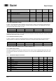
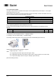
4.1 M12 flange connector, 5-pin
Pin
Assignment
Description
M12 (male)
1
CAN_GND
Ground connection relating to CAN
2
+Vs
Voltage supply
3
GND
Ground connection relating to +Vs
4
CAN_H
CAN Bus signal (dominant High)
5
CAN_L
CAN Bus signal (dominant Low)
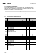
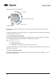
4.2 2xM12 flange connector, 5-pin
Pin
Assignment
Description
M12 (male/female)
1
CAN_GND
Ground connection relating to CAN
2
+Vs
Voltage supply
3
GND
Ground connection relating to +Vs
4
CAN_H
CAN Bus signal (dominant High)
5
CAN_L
CAN Bus signal (dominant Low)
Terminals with the same designation are connected to each other internally and identical in their functions.
Maximum load on the internal clamps Vs-Vs and GND-GND is 1 A each.
4.3 Cable
Core color
Assignment
Description
White
+Vs
Voltage supply
Brown
GND
Ground connection relating to +Vs
Green
n.c.
-
Yellow
n.c.
-
Grey
n.c.
-
Pink
CAN_H
CAN Bus signal (dominant High)
Blue
CAN_L
CAN Bus signal (dominant Low)
Red
CAN_GND
Ground connection relating to CAN