
Operating Guide

7
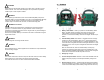
6) AC charging jack – Use the included AC charger to recharge the
internal battery through this charging jack. Only use the supplied AC
charger to charge the Jump Starter.
7) Charging Status indicator – Red LED indicates when the Jump
Starter is being recharged. When the LED turns Green the Jump
Starter is fully charged.
8) 120VAC/60Hz/100Watt Outlet – Use this for powering a variety of
120V accessories.
9) 120VAC Power LED – This indicates there is power to the 120VAC
outlet. The LED remains on even in the event of an overload.
10) Switch – Press to turn on power to the 110VAC outlet or the
Emergency LED light.
11) 12VDC Power Outlet – It provides 12VDC for powering devices.
12) Battery Cables – These cables connect the clamps to the Jump
Starter.
13) ON/OFF Switch – Located on the back of the unit. When jump starting
a vehicle, ensure the switch is in the “OFF” position before connecting
the Jump Starter to the vehicle battery. Once properly connected, turn
the switch into the “ON” position. This is located on the back on the
unit.
14) 15A Fuse – 15A over current protection for the 12VDC output port.
This is located on the back of the unit.
8
4. Operating Instructions
This unit should only be operated in locations that meet the following
conditions:
1) Dry conditions: Do not allow water or other liquids to drop or splash
on the Jump pack.
2) Cool conditions: Ambient air temperature should be between 0 and
40°C (32 and 104°F).
3) Ventilation: Leave at least 2” (5 cm) clearance around the Jump
Starter for air flow. Ensure that the ventilation openings are not
obstructed.
4) Safe: Do not operate the Jump Starter in enclosed areas where
batteries may be stored or in a compartment capable of storing
flammable liquids like gasoline.
5) Protected: Do not operate the Jump Starter where it will be exposed to
battery gasses. These gasses are very corrosive and prolonged
exposure could seriously damage the Jump Starter. Also, these gases
can combine with air in sufficient quantities and relative percentages to
create an explosion hazard.
Jump Starting procedures
1) Turn off the vehicle and all accessories.
2) Place the Jump Starter on a flat and stable surface near the battery
that needs to be jump started. Ensure that the Jump Starter power
switch is in the “OFF” position.
3) Connect the RED positive (+) clamp of the cables to the positive (+)
terminal of the engine battery.
4) Connect the BLACK Negative (-) battery cable clamp to the vehicle
chassis or engine block away from the engine battery. Do not connect
the BLACK Negative (-) battery cable clamp to the carburetor, any fuel
lines, or any sheet metal body parts. If the Reverse Polarity Red LED
illuminates, then a reverse polarity connection has been detected.
The correct polarity on the cable clamp and battery terminal
connections must be established before proceeding. Disconnect both
Jump Starter battery cable clamps from the battery and repeat steps
(3) and (4). Note also, if the vehicle’s battery voltage is less than 2.5V,
the correct clamp connection Green LED will not turn on. However,
you can still jump start the vehicle as long as the Reverse Polarity Red
LED is not on.