
Installation Manual

ParSec
Reader
Installation Manual - Issue:3 - December 1998 - Page 11
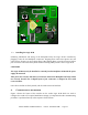
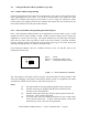
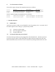
F
IG
.3 - L
OGIC
P
CB
S
WITCH
L
OCATIONS
3.3.
Installing the Logic PCB
Following installation and wiring of the Backplane PCB, the Logic PCB is installed by
plugging it onto the two Backplane connectors. Aligning these connectors requires care and
some practice because you are working blind. Mis-aligning them can result in bent or broken
pins. Press the connectors firmly home without exerting undue pressure on the Logic PCB.
CAUTIONS
The Logic PCB must only be installed or removed from the Backplane PCB with the power
supply disconnected.
Take great care to ensure that the two connectors between the Backplane and Logic PCBs
are correctly located. The L-shaped layout of the connectors is designed to assist with
correct location.
Once the two PCBs are firmly mated, refit the 2 M3 screws and washers.
4. C
OMMISSIONING THE READER
Figure 3 shows the layout of the switches on the reader Logic PCB which are used to
configure the reader to its required installation settings. It is important that the commissioning
procedure is performed strictly in the sequence which follows.
S5
S5
Tens
Tens
Units
Units
Reader ID
Reader ID
SAT
SAT
pulse
pulse
count
count
S15
S15
S3
S3
S2
S2
S9
S9
S6
S6
Reset
Reset
Range
Range
Scan
Scan
U12
U12
U1
U1
U15
U15
(SK1)
(SK1)
Keychip
Keychip
(PL1)
(PL1)
(Receiver)
(Receiver)
Antenna
Antenna
LK2
LK2
PL2
PL2
Test
Test
Scan
Scan
SR
SR
LR
LR
Power
Power
Sounder
Sounder
418MHz READER CPU
418MHz READER CPU
ISSUE 02
ISSUE 02
S1
S1
S10
S10
Tamper
Tamper
External
External
Internal
Internal
on
on
S5
S5
SAT
SAT
sub-code
sub-code
Ext
Ext
LEDs
LEDs
Buzzer
Buzzer
on
on
1
1
1
1
Buffer
Buffer
Reader
Reader
LK1
LK1
Baud
Baud