
User Manual

ParSec Reader Installation Manual - Issue:2 - January 1998 - Page 15
4.4.
Setting the Indicators & Alarm Functions
4.4.1. Indicator LED Programming
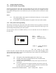
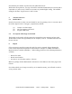
Control of the reader status indicator LEDs is set by switch S11/4. In its default position -
OFF - the LEDs are driven by the internal control lines i.e. amber for the personnel and
portable asset tags and green for static asset tag.
Power
Static
Portable
F
IGURE
5 - I
NDICATOR
LED F
UNCTIONS
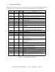
All indicator LEDs are individually programmable (except the Power/Scan LED) under the
control of switch S14; see Table 3 for details of the settings.
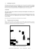
When switch S11/4 is set to ON, the LED is diverted to the main connector panel where they
can be controlled by an external voltage source; see Section 3.2, Figure 2 for details of the
connections. The external source logic is active low. In an access control application you
may wish to use external LED control to indicate if access has been granted, denied or if the
door is permanently unlocked, locked or forced.
4.4.2 Internal Sounder Programming
The internal sounder may be programmed to selectively operate on detection of conditions
generated by
(1) Portable Tags
(2) Static Tags
(3) Tamper alarms from both Portable and Static Tags.
The sounder may also be activated by external equipment generating a DC voltage between 5
& 12 volts. The activation settings are programmed by switch S4; see table 2 for details.
The volume level of the internal sounder is controlled by switch S13/1; the default setting of
OFF gives low volume, whilst ON will select high volume.
4.4.3. Alarm Relay Timer Programming
The reader is equipped with a relay which may be used to trigger external equipment or, for
example, to supply power to external sounder devices.
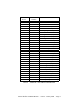
The relay can be programmed via switch S12 to de-activate after a pre-set time interval;
details are given in Table 2. Current UK legislation requires that external audible alarms shall
not be operated for longer than 20 minutes. When the internal alarm relay is used, the pulse
count setting determines when the relay is triggered, whilst switch S12 determines how long
the relay will remain latched. Note that this relay is normally operated when power is
applied to the reader. If power is lost, then the relay will de-operate and activate any external
alarm device connected to it. To meet alarm system regulations, once the relay has been