
User Manual


ParSec Reader Installation Manual - Issue:2 - January 1998 - Page 10
3.3.
Installing the Logic Pcb
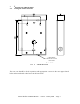
Following installation and wiring of the Backplane Pcb, the Logic Pcb is installed by plugging
it onto the two Backplane connectors. Aligning these connectors requires care and some
practice because you are working blind. Mis-aligning them can result in bent or broken pins.
Press the connectors firmly home without exerting undue pressure on the Logic PCB.
CAUTIONS
The Logic Pcb must only be installed or removed from the Backplane Pcb with the power
supply disconnected.
Take great care to ensure that the two connectors between the Backplane and Logic Pcbs
are correctly located. The L-shaped layout of the connectors is designed to assist with
correct location.
Once the two Pcbs are firmly mated, refit the M3 screw and washer.
4. C
OMMISSIONING THE READER
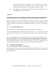
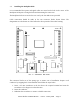
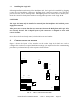
Figure 3 shows the layout of the switches on the reader Logic Pcb which are used to
configure the reader to its required installation settings. It is important that the commissioning
procedure is performed strictly in the sequence which follows.
1 2 3 4
1 2 3 4
4 3 2 4 3 2
S11
S14 S13
S4
S10
S1
S6
S5
S15
S3
S2
S12
S9
F
IG
.3 - L
OGIC
P
CB
S
WITCH
L
OCATIONS