ParSec READER INSTALLATION MANUAL Part No: IM016 Issue 2 January 1998 Newmark Technology Ltd 21-23, Ormside Way Redhill Surrey RH1 2NT United Kingdom Tel: +44(0) 1737 788800 Fax: +44(0) 1737 779535 Web site: www.newmarkworld.
ParSec READER INSTALLATION MANUAL CONTENTS 1 Caution - Static Precautions 2 General Installation Notes 2.1 2.2 2.3 2.4 2.5 3 Installing the reader 3.1 3.2 3.3 4 Reader Design Siting the reader Power Supply Requirements Communications Interfaces 2.4.1 RS-232 Data Port 2.4.2 Wiegand Data Port External PIR Operation Fixing the Reader Enclosure Installing the Backplane Pcb Installing the Logic Pcb Commissioning the Reader 4.1 4.2 4.3 4.4 4.5 4.6 Default Switch Settings Adjusting the read Range 4.
1. CAUTION - STATIC PRECAUTIONS Some devices used in the ParSec reader are static sensitive. Anti-static precautions must be taken when handling the printed circuit boards. Static discharge will permanently damage the boards. 2. 2.1. GENERAL INSTALLATION NOTES Reader Design The reader is mounted in a 2-part enclosure for surface mounting. The rear casing has 2 keyholes and 1 slotted hole for the 3 fixing screws and a variety of knock-out positions for ease of cable entry.
2.2. Siting the reader The physical location chosen to site each reader will depend principally upon (1) (2) The area of coverage required for Static Asset Tags (PS-SAT1-1’s). The exit/entry points to be protected or monitored with Portable Asset Tags (PS-PAT1-1’s) and Personnel Tags (PS-PET1-1’s). For 'portal monitoring' with PS-PAT1-1’s and PS-PET1-1’s, the reader should be sited in line with the centre of the doorway and midway between the top of the door and the ceiling.
mount the reader as high as possible or even facing downwards from the ceiling so that bodies do not shield the reader. In some cases it may be necessary to mount more than 1 reader to provide adequate coverage. (3) The readers are not weather-resistant and so must only be mounted outside in an all plastic suitably rated enclosure.
2.4.2. Wiegand Data Port (PSR-W26-1 model only) Wiegand data format allows ParSec Readers to be connected directly to access control systems using this standard. This 26-bit version uses the industry standard format as follows. Bit 1 Bits 2 - 9 Bits 10 - 25 Bit 26 Even parity on bits 1-13 Site Code as printed on tags Tag no as printed on tags Odd parity on bits 14-26 Connections for use with an InterPoint are shown below.
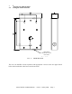
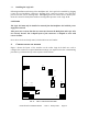
3. 3.1. INSTALLING THE READER Fixing the reader enclosure CABLE ENTRY KNOCKOUT ∅25mm IN 5 POS’NS FIG. 1 - READER REAR CASE The rear case should be fixed in position with appropriate. screws in the two upper slotted holes and secured with a third screw in the lower hole.
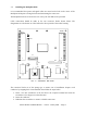
3.2. Installing the Backplane PCB It is recommended that power and signal cables are routed via the hole in the centre of the Backplane PCB prior to fixing the PCB and terminating the connectors. The Backplane PCB is secured to the rear case by the four M3 screws provided. Cable connections should be made to the two connector blocks shown below. The designations are also shown on a label affixed to the top inside of the reader housing.
TERMINAL BLOCK 1 TERMINAL NUMBER 1 2 3 4 5 6 7 8 9 10 11 12 13 14 15 +12 volt supply input 0V 0V +5 volt output Reader inhibit input Long range inhibit input Not used Wiegand data 0 (D0) out Wiegand data 1 (D1) out Wiegand inhibit input Green LED external input Amber LED external input Red LED external input External sounder input Data ground 2 1 2 3 4 5 6 7 8 9 10 11 12 13 14 15 External PIR +12V output External PIR 0V output PIR contact input RS-232 data input RS-232 data output RS-232 data ground RS
3.3. Installing the Logic Pcb Following installation and wiring of the Backplane Pcb, the Logic Pcb is installed by plugging it onto the two Backplane connectors. Aligning these connectors requires care and some practice because you are working blind. Mis-aligning them can result in bent or broken pins. Press the connectors firmly home without exerting undue pressure on the Logic PCB. CAUTIONS The Logic Pcb must only be installed or removed from the Backplane Pcb with the power supply disconnected.
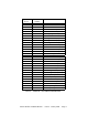
4.1. Default Switch Settings Table 2 below lists the functions of all switches on the Logic Pcb. When installing a reader for the first time, set the switches to their default conditions shown in italics in the table.
4.2. Adjusting the Read Range The range at which Portable Asset and Personnel Tags is read by the reader is adjustable from a maximum free space range of c. 25m down to a few cm. to suit the requirements of the individual installation. Notes (1) (2) The nominal 100m long range reading of Static Asset Tags is not adjustable Tamper alarms, routine reports and low battery conditions are signalled by Static and Portable Tags at high power (i.e.
case, there is always a metal screen behind the display. You may have to try several different positions on a laptop before you find one that does not impair the range. We recommend that you should always temporarily fit the tag on assets containing metal and check the range is adequate before fixing it down permanently. Once you have found the best position on, for example, a particular model of laptop, you will then be able to fit the tag in the same position for all similar models.
4.3. Setting the Reader Identity 4.3.1. Reader Number Programming Switch S2 programs the 'units value' and S3 programs the 'tens value'. Set the required values before applying power to the reader. Should the reader number need to be changed, select the new number then depress the reset switch (S15); the new number will be read by the reader software. Notes (1) (2) The reader number is only reported via the RS-232 data port; it is not reported via the Wiegand data port.
4.4. Setting the Indicators & Alarm Functions 4.4.1. Indicator LED Programming Control of the reader status indicator LEDs is set by switch S11/4. In its default position OFF - the LEDs are driven by the internal control lines i.e. amber for the personnel and portable asset tags and green for static asset tag.
operated, it cannot be re-operated until a time equal to its set time has elapsed. For example, if you set S12 for 5 minutes and a tag is read which causes it to operate for 5 minutes, then it will not operate again until a further 5 minutes have passed. 4.5. PIR Operation The default state of switch S11/1 is ON, which disables PIR usage. If either, or both internal and external PIRs are used, switch S11/1 should be set to OFF. 4.5.1.
determined by the number of pulses detected within this interval. With switch S9 in position 1, the tag's code will be transmitted immediately it is moved (this is equivalent to 1 pulse count). If this is too sensitive try another higher setting. The standard setting for the Static Tag is between 3 and 5 counts. 5. 5.1.
The information in this document is subject to change without notice and should not be construed as a commitment by Newmark Technology Limited. No responsibility is assumed by Newmark Technology Limited for any errors that appear in this document.