
Installation Manual

ParSec
Reader
Installation Manual - Issue:3 - December 1998 - Page 9
3.2.
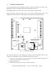
Installing the Backplane PCB
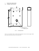
It is recommended that power and signal cables are routed via the hole in the centre of the
Backplane PCB prior to fixing the PCB and terminating the connectors.
The Backplane PCB is secured to the rear case by the four M3 screws provided.
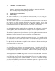
Cable connections should be made to the two connector blocks shown below. The
designations are also shown on a label affixed to the top inside of the reader housing.
TERM 1
15
1
1
15
SK1
F1
TERM 2
D1
+
C3
C4
C2
C1
RLY1
PL1
U1
Q1
D2
R1
+
D3
F
IG
. 2 - B
ACKPLANE
P
CB
L
AYOUT
The connector blocks are of the sprung type to ensure ease of installation. Prepare each
conductor by stripping back 5 mm insulation then follow the steps below.
1.
Insert a 2.5 mm screwdriver in the slot above the required terminal and twist the
screwdriver a few degrees in either direction.
2.
Insert the conductor.
3.
Withdraw the screwdriver to ensure a reliable connection.