
Installation Manual
ParSec
Reader
Installation Manual - Issue:3 - December 1998 - Page 4
1.
CAUTION - S
TATIC
P
RECAUTIONS
Some devices used in the ParSec reader are static sensitive.
Anti-static precautions must be taken when handling the printed circuit boards.
Static discharge will permanently damage the boards.
2. G
ENERAL
I
NSTALLATION
N
OTES
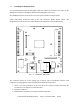
2.1. Reader Design
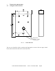
The reader is mounted in a 2-part enclosure for surface mounting. The rear casing has 2
keyholes and 1 slotted hole for the 3 fixing screws and a 25mm diameter knock-out hole in
the rear face for cable entry.
The reader contains two PCB’s for ease of installation and maintenance. The rear B
ACKPLANE
P
CB
comprises two cable termination blocks, the power supply regulator, 1A fuse, alarm
relay, and two connectors to the front L
OGIC
P
CB
. The Backplane PCB will normally remain
permanently mounted after the reader case has been sited and the cables installed.
The L
OGIC
P
CB
contains the radio receiver, the microprocessor and communications circuitry,
and the K
EY
PIC personality module. All reader adjustment and configuration is performed
via the logic PCB, which is mounted onto the Backplane PCB via two push-fit connectors.
This method of construction enables replacement of the logic PCB for maintenance purposes
and also makes it possible for the physical mounting and cabling of the reader enclosure and
Backplane to be carried out prior to system configuration and commissioning.
The reader front cover may be fitted with a recessed security screw. It is normally supplied
with a standard M3 screw fitted but alternative M3 “Torx” and Newmark type screws are also
provided. For these to be used for installation, you will need a “Torx” type TX10 screwdriver
(e.g. RS: 662-585) or a Newmark security driver (Part no SS0001 or RS part 541-983). Any
attempt to remove the front cover will operate the internal anti-tamper switch which may be
set to trigger a local or a remote alarm.
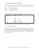
There are 2 types of reader. The model PSR-232-1 has an RS232 port and is normally used
with TransAsset or other third party asset management software. The model PSR-W26-1 has
a 26-bit industry standard wiegand card type data output and is normally used with access
control systems. It is possible to convert from 1 model to another by simply changing the
socketed KeyPIC.
All the tags transmit at 418 MHz using a power level which in the UK is MPT 1340 licence
exempt by the DTI. Tags for sale in the USA meet FCC part 15 rules. For those countries
where 418 MHz is not acceptable, for example mainland Europe tags and readers operating at
a different frequency may become available in 1999. All units are CE marked and comply
with European EMC directives. However, to maintain this compliance, it is essential that
you follow the installation procedures in this manual and in particular use grounded screened
cables where specified.