
Installation Manual

ParSec
Reader
Installation Manual - Issue:3 - December 1998 - Page 12
4.1.
Default Switch Settings
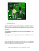
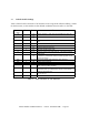
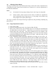
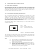
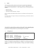
Table 2 below lists the functions of all switches on the Logic PCB. When installing a reader
for the first time, set the switches to their default conditions shown in italics in the table.
S
WITCH OR
L
INK
P
OLE
S
ENSE
F
UNCTION
S2 0-9
(
0
)
Reader
Number - Units (User set) for PSR-232-1 type only
S3 0-9
(
0
)
Reader
Number - Tens (User set) for PSR-232-1 type only
S5 Note: Only one section of this switch should be turned at a
time
1
On
2 times normal receiver gain
2
On 4 times normal receiver gain
3
On 8 times normal receiver gain
4
On 16 times normal receiver gain
S6
Press Scanner master reset (starts scanner - indicated by flashing
power LED)
S9 1-7
(
3
)
Static asset tag pulse count setting 1=1, 7=7 (8,9 & 0 unused
- default to 1); determines number of Static tag pulse counts
before data output
S10 Depressed Front panel tamper OFF (ON when cover removed)
S13 1
ON
Enable internal sounder
S13 2
ON
Enable external control of LEDs
S13
3 & 4
OFF
Position dependent on sub-system code; both must match
Static asset tag switch positions;
S15
Press Master processor and KeyPIC reset; only used in total
data/reader lock-up condition which may be caused by bad
power or other data error
LK2 Fitted Connects internal antenna to receiver. Remove when used with
external antenna
LK1 Fitted RS 232 set to 2400 baud. Remove for 9600 baud
T
ABLE
2 - L
OGIC
P
CB
S
WITCH
& L
INK
F
UNCTIONS