SENSOR-3 Installation Manual All other trademarks mentioned in this document are the property of their respective owners. © 2018 Bastille Networks. All rights reserved. NOTE: Need Bastille Trademark info and patent info plus anything else that council advises. 1 Revision 0.
REVISION HISTORY Rev Date 0.1 First draft. 10-17-18 0.2 Replaced old pictures. Added new pictures 10-26-18 0.3 Added FCC label info for Scanning Receiver function 11-19-19 0.4 Edit FCC label info 11-20-19 0.5 Corrected FCC ID for Wifi/BT module 12-03-19 0.6 Added Compliance Responsible Party information 1-03-20 0.7 Added Box Support installation section 1-30-20 0.8 Added On Ceiling Tile Installation section 2-03-20 2 Revision 0.
TABLE OF CONTENTS 1. OVERVIEW 4 2. SITE PLANNING 5 2.1. REQUIRED INFRASTRUCTURE 5 2.2. LOCATION 5 2.3. DENSITY AND DISTRIBUTION 6 2.4. SENSOR ORIENTATION 7 3. SENSOR INSTALLATION 8 3.1. DESKTOP 8 3.2. IN-CEILING 9 3.2.1. MOUNT KIT 9 3.2.1.1 SENSOR-02 ADAPTER PLATE 11 3.2.1.2 SENSOR-02 MOUNTING PLATE 12 3.2.1.3 Mounting To A Threaded Rod 15 3.2.1.4 Mounting to a Box Support 19 3.2.1.
1. OVERVIEW The Bastille Networks Sensor-3 provides protocol agnostic visibility of the Radio Frequency spectrum from 50MHz through 6GHz. It is designed for use in commercial settings where wireless security is of paramount concern and real-time threat monitoring is desired. This manual provides an overview of how to plan and install Bastille Networks Sensor to provide robust and effective coverage of the protected space. 4 Revision 0.
2. 2.1. SITE PLANNING REQUIRED INFRASTRUCTURE The Sensor requires wired network connectivity in the form of ethernet, preferably 1G-Base-T, but also 100MBase-T, and a routable path for it to reach public IPv4 address space. It can be powered by Power-OverEthernet (PoE) that is compliant to at least the 802.3at specification. Optionally, it can be powered from a DC power supply that provides 44VDC to 56VDC and a minimum of 26W of power. 2.2.
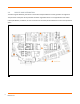
2.3. DENSITY AND DISTRIBUTION To localize signals effectively, the Sensors need to be loosely distributed in a basic geometric arrangement. The perimeter of the space to be protected should be ringed with Sensors at an approximate 15-25 meter interval (50-80 feet). In addition, at least 1 more Sensor should be placed towards the center of the protected space. ! 6 Revision 0.
2.4. SENSOR ORIENTATION The Sensor contains a number of antennae that work best when the Sensor is mounted on a horizontal plane. In a desktop or underfloor application, the Sensor should be mounted in a non-inverted orientation. In a ceiling mount or above ceiling mount application, the Sensor should be mounted in an inverted orientation. The Sensor is not designed for wall mounted applications and should not be mounted in this orientation. 7 Revision 0.
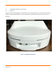
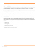
3. 3.1. SENSOR INSTALLATION DESKTOP The Sensor can be placed upright (non-inverted) directly on a smooth flat surface. The Sensor’s enclosure was designed to allow sufficient airflow to cool the system while fully operational, without any need for risers or stand offs. Figure 1. Desktop Mounted Sensor 8 Revision 0.
3.2. IN-CEILING The Bastille Networks Sensor is designed for installation in a variety of ceiling mount locations and is certified to UL2043 standard for installation in an air handling space. In all cases, the installation location should provide an adequate flow and volume of air for cooling of the Sensor, and under no circumstances should any of the case air vents be obstructed. When installing a Sensor in a ceiling location care should be taken to ensure that the Sensor is mounted securely. 3.2.1.
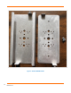
Figure 2. Bastille MOUNT-03 Kit 10 Revision 0.
3.2.1.1 SENSOR-3 ADAPTER PLATE The Adapter Plate is C-shaped aluminum piece that is pre-drilled with holes that match a variety of de facto industry standard hardware. There is an embedded nut on one end of the Adapter Plate, and a captive thumb screw on the other end.
Figure 4. Sensor-01 Mounting Plate (shown for reference only) 3.2.1.2 SENSOR-3 MOUNTING PLATE The Sensor-3 Mounting Plate is a flat piece of aluminum with tabs on the short edges that house an embedded nut and a captive thumb screw. There are two additional holes used to attach the Sensor-3 Mounting Plate to the Sensor-3 enclosure using two M5 pan head screws. The tabs should point away from Sensor-3 enclosure when properly installed, and the M5 screws should be hand tight (see Figure 5 below).
Figure 5. Sensor-3 Mounting Plate 13 Revision 0.
Figure 6. Sensor with Mounting Plate To install the Sensor-3 to the ceiling, first choose an appropriate ceiling mount structure and secure the Sensor-3 Adapter Plate to it. 14 Revision 0.
3.2.1.3 Mounting To A Threaded Rod The following example shows two nuts and two washers that are used to attach the Sensor-3 Adapter Plate to a ½” diameter threaded rod. Figure 7. Sensor-3 Adapter Plate Attached to Threaded Rod (top view) 15 Revision 0.
Figure 8. Sensor-3 Adapter Plate Attached to Threaded Rod (bottom view) Then simply slide the Sensor (with the Mounting Plate) to the Adapter Plate, making sure the thumbscrew on the Mounting Plate is on the same side as the nut on the Adapter Plate. Secure the Sensor-3 to the Adapter Plate using the two thumb screws on both ends. 16 Revision 0.
Figure 9. Insert Mounting Plate to Adapter Plate. 17 Revision 0.
Figure 10. Mounting Plate Fully Inserted to Adapter Plate. 18 Revision 0.
3.2.1.4 Mounting to a Box Support For mounting Sensors above ceiling tiles using the grid as a support, a Cooper Industries/Eaton BA50A Adjustable Box Hanger T-Bar (or equivalent) can be used, which straddles the opening of a ceiling tile, mounting to the grid rails on either side. This method may require the use of a drop wire or rod to further support the mass of the hanger and Sensor. Procedure: 1. 2. 3. 4.
Figure 12. Install Sensor Adapter Plate to Hanger Midspan 20 Revision 0.
3.2.1.5 Mounting On (Below) Ceiling The Sensor can be mounted below ceiling tiles using a Sensor Tripod Mount and two M5x10mm pan head screws (see Figure 13), a HX-T-CLIP-BA1 ceiling tile T-Bar clip from Grip Lock Systems (see Figure 14), and a ¼-20 locking nut (not shown). The HX-T-CLIP-BA1 provides a wire loop on the top for additional support if needed. Procedure: 1. Install HX-T-CLIP-BA1 to ceiling tile grid rail. See video link below – do not install ‘stopper’: https://www.youtube.
Figure 14. HTX-T-CLIP-BA1 T-Bar Clip Figure 15. Attach Sensor Tripod Mount To Clip. 22 Revision 0.
Figure 2. Attaching Tripod Mount to Sensor. 23 Revision 0.
APPENDIX A - SPECIFICATIONS Category Specification Size 298mm x 298mm x 132mm Weight 6.2 lbs Operating Environment 0 – 40°C, 0-90% RH Power Consumption 20W typical at 25°C, 25W maximum DC Input Jack 44-56V, 25W min (use CUI SD150-48-U-P5 AC Adapter or equivalent) POE 802.3at compliant Indications Ethernet LINK/ACT LED, RGB status LED Control Reset button Connectors RJ-45, Auxiliary DC Input Jack 24 Revision 0.
APPENDIX B - REGULATORY INFORMATION FCC ID: 2AIJ5-SENSOR3 CONTAINS FCC ID: PD9AX200NG Responsible Party Contact Information Bastille Networks 1000 Marietta St., #224 Atlanta, GA 30318 Phone: (800) 530-3341 Federal Communication Commission - Declaration of Conformity This equipment has been tested and found to comply with the limits for a Class A digital device, pursuant to Part 15 of the FCC Rules.