
Manual

4 BG1600M Intermittent Pilot Ignition Control with Rollout Switch Installation Instructions
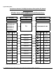
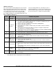
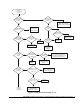
Typical Wiring Chart
TO
TO
Label
(REF)
TB
#
TB
SPADE
TB
#
TB
Label
GND
(VALVE)
5/Chassis
(frame)
Connect To 1
GND
(MV/PV)
GND
(BURNER)
5/Chassis
(frame)
Connect To 2
GND
(BURNER)
GND
(24V)
5/Chassis
(frame)
Connect To 3
GND
(24V)
THS 2 Connect To 4 24V / TH
PV 1 Connect To 5 PV
MV 3 Connect To 6 MV
R.O. SWH R1 Connect To 7 R.O. SW
SENSE 4 Connect To 8 SENSE
NC none
NC none 9 INTERN
SPARK Rajah Connect To 10 SPARK
NOTE: NC means No Connection
BG1600M01CR-1BD
G775 RJD-2
G775 RJD-14
G775 RJD-15
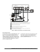
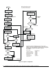
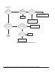
JCI (Johnson Controls) To BASO Intermittent Pilot Ignition (IPI) Control
with Rollout Switch
G77xRJx Series to BG1600M0 Series with Remote Sense
and R.O. Switch
BASO (IPI)
G775 RJD-13C
JCI (IPI)
G775 RJD-1
G770 RJA-1C BG1600M00ER-1BD
TO