
Install Instructions


H91 Model Rev. B Series Shutoff Gas Valve
© 2018 BASO Gas Products 2
Part No. BASO-INS-H91MODELREVB, Rev.- www.baso.com
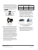
6. The H91 Series valve may be mounted on a
horizontal manifold with the solenoid coils pointed
up (vertical) or in any position not exceeding 90
from the vertical. The valve may also be mounted
on a vertical manifold in any position around its
axis (see Figure 1). Do not install the solenoid
coil upside down. Install vertically wherever
possible.
90° Maximum
from Vertical
90° Maximum
from Vertical
Limited Horizontal and Vertical
Vertical mounting may be
360º around its axis
with the gas flow either
up or down.
Figure 1: H91 Series Mounting Positions
7. Installer must be a trained, experienced, flame
safeguard control technician. Threads of the pipe
and nipples must be smooth and free of tears and
burrs. A sediment trap should also be installed in
accordance with the National Fuel Gas Code
NFPA 54 (see Figure 4). Mount the valve to the
pipework, use a quality rated pipe tape, UL listed
seal material rated for gasoline, propane, and
other gases. If not available, a quality grade pipe
dope, a light amount on the male threads, starting
two threads away from the first engaging thread. If
pipe dope lodges on the valve seat, it will prevent
proper closure. Remove excess compound after
mounting the valve to the pipework.
8. Thread pipe (the amount shown in Table 1) for
insertion into the control. Do not thread the pipe
too far. Valve distortion or malfunction may result if
the pipe is inserted too deeply.
Table 1: NPT Pipe Thread Length into Valve
Pipe Size (NPT)
or BSPT
Thread Pipe
Amount (in.)
Maximum
Depth Pipe (in.)
1/2 3/4 1/2
3/4 13/16 3/4
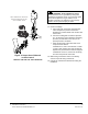
9. For any threaded connections, threads of pipe and
nipples must be smooth and free of tears and
burrs. Steam clean all piping inside diameter to
remove foreign substances such as cutting oil or
thread chips before installing into the valve. Apply
a moderate amount of good quality pipe
compound (do not use Teflon tape) to pipe only,
leaving two end threads bare (see Figure 2). On
LP installation, use compound resistant to LP gas.
APPLY A MODERATE AMOUNT OF
PIPE COMPOUND TO PIPE ONLY
(LEAVE TWO END THREADS BARE),
CAUTION: EXCESSIVE COMPOUND
MAY BLOCK DISC OFF VALVE
SEAT CAUSING LEAKS.
CORRECT WRONG
Figure 2 Use a Moderate Amount
of Pipe Compound
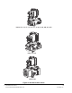
10. Connect pipe to gas control inlet and outlet. Use a
wrench on the square ends of the control. If a
flange is used, place the wrench on the flange
rather than on the control. This process should be
used for both the installation and removal of the
valve in a gas system. (see Figure 3)