
Install Instructions

H91 Model Rev. B Series Shutoff Gas Valve
© 2018 BASO Gas Products 5
Part No. BASO-INS-H91MODELREVB, Rev.- www.baso.com
Wiring
!
WARNING: Risk of Shock.
Disconnect the power supply before making
electrical connections to avoid electrical shock or
equipment damage. Ensure that the operating
voltage is identical to the information on the product
identification label.
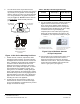
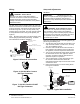
The H91 Series valve is supplied with 3-tab and 2-tab
electrical connections. The tabs of the solenoid coil are
male tag terminals, and electrical connections should
be made using 1/4 in. (6.35 x 0.8 mm) female, fully
insulated push-on terminals. The earth ground terminal
is clearly labeled with the earth ground symbol (see
Figure 5).
Note: Electrical connections can also be made using
electrical plugs (DIN 43650 [ISO 4400]). Available
from a BASO Gas Products distributor.
Non-Polarity Sensitive
Connections
Ground Tab
25 VDC, 25V, 120V and 240V Only
1
L1 (Hot)
L2 (Neu)
1
Power supply provides disconnect
means and overload protection
as required.
Safety
Control
24 Volt
Thermostat
Limit(s)
Figure 5: Electrical Connections
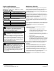
Figure 6: SVC200 Wire Connect
DIN Type Connector
Figure 7: SVC210 Conduit 1/2 NPT
DIN Type Connector
Setup and Adjustments
Checkout
IMPORTANT: All adjustments must be
made in conjunction with the gas appliance and in
accordance with the appliance manufacturer’s
instructions. Only authorized personnel should make
adjustments.
!
WARNING: Risk of Explosion or Fire.
Follow this or an equivalent checkout procedure
after installation. Before leaving the installation,
verify that the gas valve functions properly and that
the system has no gas leaks. Gas leaks can lead to
an explosion or fire, and may result in severe
personal injury or death.
Make sure all components are functioning properly by
performing the following test.
1. Test all joints and connections for leaks with a rich
soap and water solution. If leaks occur, see Step
11 in the Installation section.
2. Close the main manual shutoff valve and wait at
least 5 minutes for unburned gas to escape from
the appliance, and then reopen the shutoff valve.
3. Turn on the main electrical power switch and close
the thermostat contacts. The appliance should
operate in accordance with the manufacturer’s
specified sequence of operation.
4. Turn the thermostat to a low dial setting to open
the contacts. All burner flames should be
extinguished. Repeat Steps 3 and 4 in this section
at least three times.
5. Return the thermostat to a normal setting before
leaving the installation.
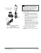
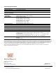
X
indicates possible
locations for other controls.
Gas Flow
Shutoff Valve
H91 Series
Gas Valve
X
X
Sediment
Trap
3 in. (76.2 mm)
Minimum
Burner
Direction
of Flow
PRESS
TAP
OUTIN
Figure 8: Typical H91 Installation