
User`s manual

Physical Interface AW00089316000
64 Basler ace GigE
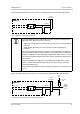
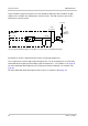
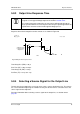
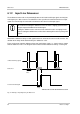
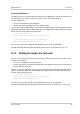
Figure 39 shows a typical circuit you can use to monitor the output line with an LED or an opto-
coupler. In this example, the voltage for the external circuit is +24 VDC. Current in the circuit is
limited by an external resistor.
By default, the camera’s Exposure Active signal is assigned to Output Line 1.
The assignment of a camera output signal to Output Line 1 can be changed by the user. For more
information about assigning camera output signals to Output Line 1, see Section 6.2.1 on page 70.
For more information about output line pin assignments and pin numbering, see Section 5.2 on
page 50.
For more information about the Exposure Active signal, see Section 7.10 on page 127.
1
2
3
4
5
6
6-Pin
Receptacle
I/O_Out_1
I/O_Gnd
Out_1_Ctrl
Camera
Your Gnd
LED
Output
to You
+24
VDC
Your Gnd
2.2k
Fig. 39: Typical LED Output Signal at +24 VDC for the External Circuit (Simplified Example)