
User`s manual

Physical Interface AW00089316000
58 Basler ace GigE
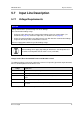
Voltage Levels When a PLC Power and I/O Cable is Used
The following requirements apply to the camera’s I/O input (pin 2 of the 6-pin connector) when a
PLC power and I/O cable is used. The PLC power and I/O cable will adjust the voltages to the levels
required by the camera’s I/O input (see Table 9).
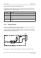
5.7.2 Characteristics
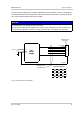
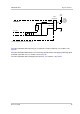
The camera is equipped with one physical input line designated as Input Line 1. The input line is
accessed via the 6-pin receptacle on the back of the camera.
As shown in Figure 34, the input line is opto-isolated. See the previous section for input voltages
and their significances. The absolute maximum input voltage is +30.0 VDC. The current draw for
each input line is between 5 mA and 15 mA.
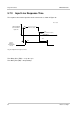
Figure 35 shows an example of a typical circuit you can use to input a signal into the camera.
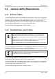
Voltage Significance
+0 to +24 VDC Recommended I/O input voltage.
+0 to +8.4 VDC The voltage indicates a logical 0.
> +8.4 to +10.4 VDC Region where the transition threshold occurs; the logical state is not defined in this
region.
> +10.4 VDC The voltage indicates a logical 1.
+30.0 VDC Absolute maximum; the camera may be damaged when the absolute maximum is
exceeded.
Table 10: Voltage Requirements When Using a PLC Power and I/O Cable
1
2
3
4
5
6
6-Pin
Receptacle
I/O_In_1
I/O_Gnd
In_1_Ctrl
Camera
10
Fig. 34: Input Line Schematic (Simplified)
Current
Limiter