
User`s manual

AW00089316000 Physical Interface
Basler ace GigE 57
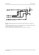
5.7 Input Line Description
5.7.1 Voltage Requirements
:
Voltage Levels When the Standard Power and I/O Cable is Used
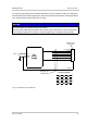
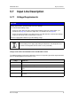
The following voltage requirements apply to the camera’s I/O input line (pin 2 of the 6-pin connector)
when a standard power and I/O cable is used:
NOTICE
Voltage outside of the specified range can cause damage.
The recommended voltage range
for the input line differs from the recommended voltage ranges for camera power (see
Section 5.5 on page 55) and for the output line (see Section 5.8.1 on page 62).
for the I/O input line of Basler ace GigE cameras can differ from the recommended voltage
ranges for the I/O input lines of other Basler cameras.
You must supply power within the specified voltage range.
Different voltage levels apply, depending on whether the standard power and
I/O cable or a PLC power and I/O cable is used (see below).
Voltage Significance
+0 to +24 VDC Recommended I/O input voltage.
+0 to +1.4 VDC The voltage indicates a logical 0.
> +1.4 to +2.2 VDC Region where the transition threshold occurs; the logical state is not defined in this
region.
> +2.2 VDC The voltage indicates a logical 1.
+30.0 VDC Absolute maximum; the camera may be damaged when the absolute maximum is
exceeded.
Table 9: Voltage Requirements When Using the Standard Power and I/O Cable