
User`s manual


AW00089316000 Physical Interface
Basler ace GigE 49
5 Physical Interface
This chapter provides detailed information, such as pinouts and voltage requirements, for the
physical interface on the camera. This information will be especially useful during your initial
design-in process.
5.1 General Description of the
Camera Connections
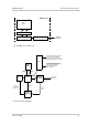
The camera is interfaced to external circuitry via connectors located on the back of the housing:
An 8-pin, RJ-45 jack used to provide a 100/1000 Mbit/s Ethernet connection to the camera.
Since the camera is Power over Ethernet capable, the jack can also be used to provide power
to the camera.
A 6-pin receptacle used to provide access to the camera’s I/O lines and to provide power to the
camera (if PoE is not used).
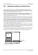
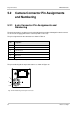
Figure 31 shows the location of the two connectors.
8-pin
RJ-45
Jack
6-pin
Receptacle
Fig. 31: Camera Connectors