Basler IP Fixed Dome Cameras User’s Manual for BIP2-DXXXXc-dn Models Document Number: AW001015 Version: 07 Language: 000 (English) Release Date: 14 April 2014
Contacting Basler Support Worldwide Europe and the Middle East: Basler AG An der Strusbek 60 - 62 22926 Ahrensburg Germany Phone: +49 4102 463 515 Fax: +49 4102 463 599 Email: support.europe@baslerweb.com The Americas: Basler, Inc. 855 Springdale Drive, Suite 203 Exton, PA 19341 U.S.A. Phone: +1 610 280 0171 Fax: +1 610 280 7608 Email: support.usa@baslerweb.com Asia: Basler Asia Pte.
AW00101507000 Table of Contents Table of Contents 1 Introduction . . . . . . . . . . . . . . . . . . . . . . . . . . . . . . . . . . . . . . . . . . . . . . . . . . . . . 1 1.1 About this Document . . . . . . . . . . . . . . . . . . . . . . . . . . . . . . . . . . . . . . . . . . . . . . . . . . . 1 1.2 Precautions . . . . . . . . . . . . . . . . . . . . . . . . . . . . . . . . . . . . . . . . . . . . . . . . . . . . . . . . . . 2 1.3 Overview. . . . . . . . . . . . . . . . . . . . . . . . . . . . .
Table of Contents AW00101507000 Appendix A Software License Information . . . . . . . . . . . . . . . . . . . . . . . . . . . . . . . . .115 Revision History . . . . . . . . . . . . . . . . . . . . . . . . . . . . . . . . . . . . . . . . . . . . . . . . . . . . . . . . . . 117 Index . . . . . . . . . . . . . . . . . . . . . . . . . . . . . . . . . . . . . . . . . . . . . . . . . . . . . . . . . . . . . . . . . . . .
AW00101507000 Introduction 1 Introduction 1.1 About this Document Applicability This document applies to cameras that have the designation "BIP2" as part of their model name. See the specification tables in Section 8 on page 109 for a complete list of the camera models covered by this document. This document is intended for administrative users of the camera. Previous experience with networking will be a great help when using this document.
Introduction AW00101507000 1.2 Precautions WARNING The camera is not designed for unprotected use in an explosive atmosphere. If you use the camera in an explosive atmosphere, it must be enclosed within an appropriate environmental housing. CAUTION Electrical Shock Hazard Touching the camera’s internal components may result in an electrical shock. Do not open the camera housing. The housing contains no user serviceable parts.
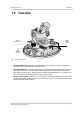
AW00101507000 Introduction 1.3 Overview RJ-45 Network / PoE RS-485 Terminal Block Main Terminal Block Fig. 1: Camera Connections RJ-45 Network / PoE - Provides a 10/100 Ethernet connection and can be used to connect Power over Ethernet (IEEE 802.3af) to the camera. Main Terminal Block - Provides connections for an alternate camera power input that can be used to power the camera instead of PoE (on outdoor camera models only).
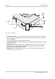
Introduction AW00101507000 Status Indicator LEDs Audio Connector Factory Default Button SD Card Slot Fig. 2: Camera Connections Status Indicator LEDs - The green LED indicates the network connection speed. Off means the network speed is 10 MBits/s (or the network is not connected). On means the network speed is 100 MBits/s. The yellow LED indicates the level of network activity. Factory Default Button - Used to return the camera to factory default settings.
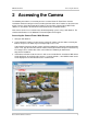
AW00101507000 Accessing the Camera 2 Accessing the Camera The following instructions assume that you have used the Basler IP Fixed Dome Camera Installation Guide to install your camera and that you know either the IP address or the host name of your camera. (If you don’t know the IP address you can find it using the Basler BIP Finder software as described in the Basler IP Fixed Dome Camera Installation Guide.) Your camera can be accessed from most standard operating systems using a web browser.
Accessing the Camera 6 AW00101507000 Basler IP Fixed Dome Cameras
AW00101507000 Configuring the Camera 3 Configuring the Camera This section describes how to configure your camera. It is intended to be used by administrators who have full access rights to the camera. 3.1 Introduction When adjusting the parameters used to configure the camera, it helps to have an overview of the camera’s functionality in mind. Figure 3 on page 9 shows a block diagram of the camera outlining the basic functional units in the camera and shows how they are related.
Configuring the Camera AW00101507000 Controls, Streaming, Motion Detection, Alarm Handling, etc. Except for the Streaming group, the parameters in each group can be adjusted while the camera is in normal mode. The parameters in the Streaming group can only be adjusted when the camera is in "configuration" mode. When you open the Streaming parameters group in the web client, the camera will automatically be placed in the configuration mode.
AW00101507000 Configuring the Camera Network Parameters Camera Web Server Microprocessor Stream 0 Parameters Stream 0 Encoder Alarm Parameters Image Control Parameters Imaging Sensor Motion Detection Parameters I/O Parameters System Parameters H.264, MPEG 4 or MJPEG Stream 1 Parameters H.
Configuring the Camera AW00101507000 3.2 Accessing the Configuration Tools and Camera Parameters 1. If you have not already done so, start your web browser and access the Basler Surveillance Web Client in your camera as described in Section 2 on page 5. 2. When the Basler Surveillance Web Client opens as shown below, click the Configuration button on the left side of the Basler tool bar.
AW00101507000 Configuring the Camera 3. A Camera Configuration menu will open on the left side of the client as shown below. Notice that the parameters used to configure the camera appear in groups such as the Image Controls group and the Streaming group. You can open a parameter group by clicking the + sign beside the group name. By default, the camera is set so that video stream 0 is an MJPEG stream, and a Live Stream 0 tab will appear in the client as shown below.
Configuring the Camera AW00101507000 refresh rate. Opening and closing parameter groups or switching from one tab to another will work very slowly if the refresh rate is too high. Plug-in Help - Click the Plug-in Help button to get information about installing the plugins needed to view live streams in your web browser. Manual Selection - Click the Manual Selection button to zoom into or out of the streamed image by using the mouse wheel.
AW00101507000 Configuring the Camera low optical contrast (e.g. a white wall) contaminated lens The focus can be readjusted, if necessary, through the Focus tab in the Image Controls group (see Section 3.3.4 on page 19).
Configuring the Camera AW00101507000 3.3 Image Control Parameters The parameters in the Image Controls group control the quality of the images captured by the camera's imaging sensor. 3.3.1 Exposure Tab Exposure Mode - Sets the camera’s exposure mode. Prioritize None = Automatic exposure time control and automatic gain control are both enabled. The camera will automatically adjust both the exposure time and the gain to maintain good overall image quality as lighting conditions change.
AW00101507000 Configuring the Camera Exposure Offset - Is used to customize the operation of the camera’s automatic controls. Negative settings will bias the auto controls toward producing darker images. Positive settings will bias the auto controls toward producing lighter images. Backlight Compensation - Check the box to enable the camera’s backlight compensation feature. This feature automatically compensates when the main lighting comes from behind the image subject.
Configuring the Camera AW00101507000 Gain Limit - When automatic gain control is enabled (see Exposure Mode above), the Gain Limit parameter sets the maximum amount of gain that the automatic gain control can use. If the Gain Limit is set to "Off", there will be no limit for the automatic gain control. Gain - When automatic gain control is disabled (see Exposure Mode above), the Gain parameter sets the gain for the captured images.
AW00101507000 Configuring the Camera Fluorescent I = The camera will automatically change the white balance settings so that they are biased for normal fluorescent lighting (a color temperature of 2700 K). Once the settings are changed, the white balance will stay fixed at that point. Fluorescent II = The camera will automatically change the white balance settings so that they are biased for bright fluorescent lighting (a color temperature of 4000 K).
Configuring the Camera AW00101507000 IR Filter State - Indicates the current state of the camera’s IR-cut filter. Night = The IR-cut filter is currently in the night position (filter is not in front of the sensor). Day = The IR-cut filter is currently in the day position (filter is in front of the sensor). IR Filter Switch Level - When the IR Filter Mode parameter is set to auto, the IR Filter Switch Level setting is mainly used to adjust when the camera will switch from day mode to night mode.
AW00101507000 3.3.4 Configuring the Camera Focus Tab Note: The focus tab is only available on camera models with autofocus functionality. For more information, refer to the specification tables in Section 8 on page 109. Focus Position - Indicates the relative focus position between near (N) and far (F). Focus Move - Moves the focus stepwise. You can use the Focus Move buttons to readjust the focus, if necessary.
Configuring the Camera AW00101507000 3.4 Streaming Parameters The parameters in the Streaming group are used to control the characteristics of the image area that will be captured by the camera’s sensor. They are also used to control the characteristics of the video streams that are output from the camera. The camera can produce up to three individually configured video streams. The streams are designated as stream 0, stream 1, and stream 2. Stream 0 is always enabled.
AW00101507000 3.4.1 Configuring the Camera Global Tab The parameters on the Global tab control the way that the camera’s imaging sensor will capture images. Because the images captured by the sensor are used for all three video streams, the parameters on this tab are considered to be "global", i.e., changes made here will affect what you can do when you work with the individual stream parameters. Some of the parameters in this group are used to set the imaging sensor’s "area of interest" (AOI).
Configuring the Camera AW00101507000 Frame Rate Mode - Sets the rate at which the camera’s sensor will capture frames (images). For example, selecting 30 FPS means that the camera’s imaging sensor will capture 30 frames per second. You should use this parameter to set the frame rate mode when the Function parameter on the Digital I/O tab is set to "External Trigger" (see page 58).
AW00101507000 Configuring the Camera Test Image Mode - Enables or disables the camera’s test image feature. When the test image mode is enabled, the camera will generate test images using its digital devices rather than the imaging sensor. The generated test images will be transmitted on all enabled streams. Test images are useful for troubleshooting the camera’s basic functionality and the network connection. Off = The test image function is disabled. On = The test image function is enabled.
Configuring the Camera AW00101507000 Sensor AOI Editor - Whenever the Global tab is selected, the Sensor AOI Editor tab will also be available as shown below. You can use the editor to set the sensor AOI size and position rather than entering numbers in the boxes on the Global tab. To set the sensor AOI with the editor, simply use your mouse to drag the edges of the rectangle that represents the sensor AOI. If the AOI is set to the full size of the sensor area in the editor, you won’t see a rectangle.
AW00101507000 Configuring the Camera White Balance Mask - Click the White Balance Mask button to open the White Balance Mask Editor as shown below. The white balance mask defines the area(s) of the image that will be used by the camera’s automatic white balancing function when the White Balance Mode parameter is set to Auto (see Section 3.3 on page 14).Only the areas highlighted in the editor will be included in the white balance mask.
Configuring the Camera AW00101507000 Auto Brightness Mask - Click the Auto Brightness Mask button to open the Auto Brightness Mask Editor as shown below. The auto brightness mask defines the area(s) of the image that will be used by the camera when it performs automatic exposure, gain, and iris control (see Section 3.3 on page 14). Only the areas highlighted in the editor will be included in the auto brightness mask.
AW00101507000 Configuring the Camera Privacy Mask - Click the Privacy Mask button to open the Privacy Mask Editor as shown below. The privacy mask defines the area(s) of the image that will be blacked out in the images in the video streams. Only the areas highlighted in the editor will be included in the privacy mask and will be blacked out. To highlight an area within the editor, use the tools described under "Mask Editor Tools" on page 29.
Configuring the Camera AW00101507000 Motion Mask - Click the Motion Mask button to open the Motion Mask Editor as shown below. The motion mask defines the area(s) of the image that will be used for the camera’s motion detection function (see Section 3.5 on page 41). Only the areas highlighted in the editor will be included in the motion detection mask and used for motion detection. To highlight an area within the editor, use the tools described in the following section.
AW00101507000 Configuring the Camera Mask Editor Tools To apply a mask, all editors use the same tools. These are arranged in a toolbar at the top of each editor’s tab. With the tools, you can mask the entire sensor area, a single area or several different areas within the image. Load Saved Mask from Camera Loads the mask settings that are currently saved on the camera and displays them in the editor. Save Mask to Camera Saves the current mask settings to the camera.
Configuring the Camera 3.4.2 AW00101507000 Stream Tabs The parameters on the Stream 0 tab, Stream 1 tab, and Stream 2 tab control the way that the video stream associated with the selected tab is configured. This section describes the settings on the Stream 0 tab, the settings available on the Stream 1 and Stream 2 tabs are identical to the Stream 0 tab. Some of the parameters on each stream tab are used to set the "area of interest" (AOI) for the video stream controlled by the tab.
AW00101507000 Configuring the Camera Encoder Type - Sets the video encoder type for the stream. Off = The video stream is disabled and no images will be streamed. This setting is only available on the Stream 1 and Stream 2 tabs. Stream 0 is always enabled, and the off setting is not available for this stream. JPEG = The camera will use motion JPEG (MJPEG) encoding for the images streamed. The motion JPEG format uses standard JPEG still images to create the video stream.
Configuring the Camera AW00101507000 Encoder Type - (continued from previous page) YUV (RT triggered) = The camera will use the I420 color format for outputting uncompressed YUV images. The output will be an HTTP stream. Live recording is also supported. This encoder type is available when using the camera’s real-time trigger feature. For more information about the real-time trigger feature, see Section 7 on page 103.
AW00101507000 Configuring the Camera If the Encoder Mode parameter is set to Capped VBR, you can also set the desired quality of the stream by using the Quality parameter. Note that the effect of the quality setting is not precisely equivalent for each encoder type. For example, a quality setting of 50 will have a slightly different effect when the Encoder Type parameter is set to JPEG than it will have when it is set to MPEG4 or to H.264.
Configuring the Camera AW00101507000 Output Size - Lets you select from a list of standard image sizes. When you select a size, the camera checks the setting of the Output Scaling parameter. It then automatically sets the Stream AOI Left, Stream AOI Top, Stream AOI Width, and Stream AOI Height parameters so that the AOI will be centered on the sensor and set to the correct width and height to result in output images of the size you selected.
AW00101507000 Configuring the Camera Stream AOI Left - As shown in Figure 5 on page 30, sets the left offset (in pixels) for the stream AOI, i.e., how far the stream AOI will be offset from the left edge of the image area captured by the camera’s sensor. When you adjust this setting, you will notice that it must be changed in certain fixed increments. * Stream AOI Top - As shown in Figure 5 on page 30, sets the top offset (in pixels) for the stream AOI, i.e.
Configuring the Camera AW00101507000 GOP Length [ms] - If the Encoder Type parameter is set to H.264 or MPEG4, then the GOP Length parameter will set the time between I-frames in milliseconds. In an H.264 or an MPEG stream, the camera transmits periodic I-frames and transmits several P-frames between each I-frame. I-frames carry complete information for a captured image. P-frames only carry information about the areas of the image that have changed since the last I-frame was transmitted.
AW00101507000 Configuring the Camera Overlay Text - Sets the text that will appear in the text overlay. You can enter simple strings of text, and you can also enter the following expressions: $date$ = display the current date, time, and time zone (see Section 3.12.2 on page 74 to set the current date, time, and time zone and to set the date/time format). $timestamp$ = display timestamp (sec:µsec since 1970). $counter$ = display frame counter.
Configuring the Camera AW00101507000 $SysInfo.FirmwareVersion$ = display the camera’s firmware version info. $SysInfo.ManName$ = display the camera vendor’s name. $SysInfo.Serial$ = display the camera’s serial number. $SysInfo.MACAddress$ = display the camera’s MAC address. $System.DateTimeFormat$ = display the current date/time format setting. $Network.RxTraffic$ = display the current incoming network traffic level in kilobits/s. $Network.
AW00101507000 Configuring the Camera +Framecount - Click the +Framecount button to quickly enter the $counter$ expression into the Overlay Text line. +Hostname - Click the +Hostname button to quickly enter the $Network.HostName$ expression into the Overlay Text line. +Image - Click the +Image button to quickly enter the $image$ expression into the Overlay Text line. For more information on using images in stream overlays, see "Using Images in Stream Overlays" on page 39 below.
Configuring the Camera AW00101507000 Stream AOI Editor - Whenever a stream tab is selected, a Stream AOI Editor screen will also be available as shown below. Rather than setting numbers in the boxes on the stream tab, you can use the editor to set the AOI size and position for the stream. To set the stream AOI with the editor, simply use your cursor to drag the edges of the red rectangle that represents the stream AOI.
AW00101507000 Configuring the Camera 3.5 Motion Detection Parameters The parameters in the Motion Detection group are used to control the operation of the camera’s motion detection function. To understand what the parameters in this group do, you should have a basic idea about how motion detection works: Just before the camera captures a new image, it takes the last few captured images (from its memory) and uses them to create an averaged image called a "history image".
Configuring the Camera AW00101507000 Motion Threshold - Sets a threshold for motion detection. If the number of changed pixels in the current image is above the motion threshold and below the motion limit (see the next parameter), then motion will be detected. Motion Limit - Sets a limit for motion detection. If the number of changed pixels in the current image is above the motion threshold (see the previous parameter) and below the motion limit, then motion will be detected.
AW00101507000 Configuring the Camera 3.6 Alarm Handling Parameters The parameters in the Alarm Handling group are used to select the sources that can declare an alarm condition and to control the actions that will be taken when an alarm condition is declared. 3.6.1 Alarm Sources Section The alarm sources section of the alarm handling parameters group is used to select the sources that can declare an alarm condition.
Configuring the Camera AW00101507000 Motion Tab Source Enable - Check the Source Enable box on the Motion tab to enable motion detection as a source for declaring an alarm condition. If motion detection is enabled as an alarm source and motion is detected, an alarm condition will be declared. (In order to use motion detection as an alarm source, motion detection must be enabled. See Section 3.5 on page 41 for more information about motion detection.
AW00101507000 3.6.2 Configuring the Camera Alarm Buffers Section Each video stream can have an alarm buffer. Normally, the alarm buffer on a stream is simply a ring buffer that stores the last N captured images for the stream (N depends on the size of the images being encoded and the size of the buffer). If an alarm condition is declared, however, the alarm buffer will only continue to buffer post alarm images until the part of the buffer that is allocated for post alarm buffering is full.
Configuring the Camera 3.6.3 AW00101507000 Alarm Actions Section The alarm actions section of the alarm handling parameters is used to control the actions that will be taken when an alarm condition is declared. Digital Output Tab Action Enable - Checking the Action Enable box on the Digital Output tab enables setting the state of a camera I/O port as an action to take when an alarm condition is declared. If an alarm condition is declared, the port will be set to active.
AW00101507000 Configuring the Camera Email Password - Enter a password for authentication on the SMTP server. Up to 29 characters can be used. All standard keyboard characters are valid. Email From - Enter an email address to appear as the sender’s address in the email sent by the camera. You can use the variable $hostname$ as part of the address, and the variable will be replaced with the camera’s actual host name.
Configuring the Camera AW00101507000 MotionLevel_0= = current motion level (number of changed pixels) in region 0. The parameter descriptions for the remaining parameters MotionRegion_1/MotionLevel_1 to MotionRegion_4/MotionLevel_4 are identical to the MotionRegion_0/MotionLevel_0 parameter descriptions. HTTP URL Alarm End - Enter a valid URL. You could, for example, enter this URL: http://MyServer/cgi-bin/alarm.cgi The transmitted string will be URL encoded.
AW00101507000 Configuring the Camera FTP Password - Enter a password for authentication on the FTP server. Up to 29 characters can be used. All standard keyboard characters are valid. Live Recording Tab Action Enable - Check the Action Enable box on the Live Recording tab to enable saving a live stream file to the SD card or to an FTP server as an action to take when an alarm condition is declared. You can save several enabled streams to the SD card or to an FTP server simultaneously.
Configuring the Camera AW00101507000 SD Card Tab Action Enable - Check the Action Enable box on the SD Card tab to enable saving a file to the SD card as an action to take when an alarm condition is declared. The file saved to the SD card when an alarm condition is declared will be a text file that includes information such as the camera host name and the date and time. Include Image - Check the Include Image box to save an image file to the SD card along with the text file.
AW00101507000 Configuring the Camera 3.7 Live Recording Parameters The parameters in the Live Recording group are used to configure the settings for saving live recording data to an SD card or to an FTP server. 3.7.1 Stream Tabs The parameters on the Stream 0 tab, Stream 1 tab, and Stream 2 tab control the way that the live stream associated with the selected tab is saved and to which location it is saved. Several streams can be saved simultaneously.
Configuring the Camera AW00101507000 Storage Location - Sets the location where the live stream should be saved. SD Card = The live stream will be saved to an SD card. For information about the SD card settings, see page 52. FTP Server = The live stream will be saved to an FTP server. For information about the FTP server settings, see page 53. Video File Length [s] - Sets the maximum length in seconds of an individual live stream video segment saved to the SD card or to the FTP server.
AW00101507000 Configuring the Camera file structure for the SD card. The browser functionality will allow you to navigate through the SD card’s file structure and to download files from the SD card. Erase SD Card - Click the Erase SD Card button to erase the contents of the SD card. If the SD card cannot be accessed at the file system level, it will be reformatted in this case. When you click the button, an Are you sure? window will open.
Configuring the Camera AW00101507000 3.8 Network Parameters The parameters in the Network group are used to set the camera’s IP configuration. 3.8.1 Settings Tab Zero Configuration - Check the Zero Configuration box to enable the camera to acquire a dynamic IP address in the 169.254.0.0/16 IP subnet, which is reserved for networking within the local network. By default, the Zero Configuration box is checked. DHCP - Check the DHCP box to enable camera IP addressing via a DHCP server.
AW00101507000 Configuring the Camera Search Domain - Sets the domain names the camera will use for resolving non-fully qualified host names via DNS lookups. Multiple domain names can be defined, which have to be separated by a space. HTTP Port - Sets the HTTP port on which the web interface will listen. Commit - Click the Commit button to save any changes you have made to the network settings. Revert - Click the Revert button to cancel any changes you have made to the network settings.
Configuring the Camera AW00101507000 Commit - Click the Commit button to save any changes you have made to the RTSP settings. Revert - Click the Revert button to cancel any changes you have made to the RTSP settings. The settings will revert to what they were the last time that the Commit button was clicked. 3.8.3 QoS Tab The parameters on this tab are used to set network traffic prioritization settings, commonly known as QoS or Quality of Service settings.
AW00101507000 3.8.5 Configuring the Camera SNMP Tab SNMP Enable - Check the SNMP Enable box to enable the camera’s SNMP agent. This agent is used to receive information via the Simple Network Management Protocol (SNMP) from a "manager", e.g. an external SNMP server. In this scenario, the SNMP server tells the camera that it is still available (heartbeat functionality). For this purpose, the server sends a heartbeat timeout value ("kick") to the SNMP agent in the camera.
Configuring the Camera AW00101507000 3.9 Input / Output Parameters The parameters in the Input/Output group are used to configure the camera’s digital I/O ports and to configure the camera’s RS-485 serial port. 3.9.1 Digital I/O Tab I/O Sub-Tabs The Digital I/O tab includes two sub-tabs. Each sub-tab is used to configure one of the camera’s I/O ports. The two I/O ports are designated as I/O 0 and I/O 1. Each I/O port can be set to act as either an input or an output.
AW00101507000 Configuring the Camera External Trigger = The external trigger function is used to control the exposure start without having to use any other parameters. If the Function parameter of an input port is set to "External Trigger" and no external trigger is applied, the camera immediately stops grabbing images.
Configuring the Camera AW00101507000 sensor information in the specification tables in Section 8 on page 109. For general information about shutters, see Section 3.9.1.1. Flash Window - This option is only available for cameras with rolling shutters. You can manually adjust the Strobe Delay and Strobe Duration parameters (see below) in order to control the length of the strobe pulse. For more information, see "Using the Flash Window (Rolling Shutter)" on page 62.
AW00101507000 Configuring the Camera Rolling Shutter On cameras equipped with a rolling shutter, the pixel lines are exposed with a temporal offset (called tRow) from one line to the next. When frame start is triggered, the camera begins exposing the top line of pixels of the AOI (line one). Then, the camera begins exposing line two tRow later. And so on until the bottom line of pixels is reached. See Figure 6. The exposure time is the same for all lines.
Configuring the Camera AW00101507000 Using the Flash Window (Rolling Shutter) To provide the best-possible lighting conditions, apply the additional lighting during the "flash window" of each frame. The flash window is the period of time during a frame acquisition when all of the lines in the sensor are being exposed. See Figure 7.
AW00101507000 Configuring the Camera You can calculate when the flash window will open (i.e., the time from the frame trigger until the moment when the window opens) using the following formula: Time to Flash Window Open = tRow x (H - 1) where H = Sensor Height (user-settable AOI height + 8) tRow = Camera-specific Value (see Table 1) You can calculate the flash window width (i.e.
Configuring the Camera AW00101507000 Using Exposure Active (Rolling Shutter) When the Strobe Mode parameter is set to "Exposure Active", the camera sends a signal on the digital output port that can be used to control an external light source in order to provide additional lighting, e.g. an LED lamp. This signal is called the exposure active signal. In this scenario, the exposure active signal is active from the start of exposure of the first sensor row until the end of exposure of the last sensor row.
AW00101507000 3.9.2 Configuring the Camera Serial I/O Tab The parameters on the Serial I/O tab are used to configure the camera’s RS-485 serial port. Forwarding - Check the Forwarding box to enable serial port forwarding. When forwarding is enabled, serial commands issued via TCP/IP over the designated port (see the Port parameter below) will be forwarded to the serial port. Forwarding Mode - Sets the mode for serial port forwarding.
Configuring the Camera AW00101507000 3.10 User Parameters The parameters in the User group are used to manage user authentication on the camera. 3.10.1 Enabling Authentication and Logging in for the First Time Authentication enabled - Check the Authentication enabled box to enable user authentication on the camera. With user authentication enabled, a valid user name and password will be required to access the camera.
AW00101507000 Configuring the Camera To disable user authentication, make sure that you have logged in as an administrator and simply uncheck the Authentication enabled box. 3.10.2 Logging In and Logging Out Once you have logged into the camera, a Logged in: indicator, a Change Password button, and a Logout button (shown circled in red below) will appear in the Basler tool bar.
Configuring the Camera AW00101507000 If you are logged into the camera, refreshing the browser or closing the browser window will not log you out. You will remain logged in until you follow the log out procedure or restart the camera. 3.10.3 Managing Users To manage users, you must be logged into the camera as an administrator. Once you are logged in, access the User parameters group, and click on the Manage Users button. A User Management tab will appear as shown below.
AW00101507000 Configuring the Camera The available user levels are described in Table 2. User Level Meaning Administrator Can change all camera configuration parameters. Can add or delete users. Can change the level or password of all existing users. Viewer Can view images and can change his or her own password. Has no access to camera parameters.
Configuring the Camera AW00101507000 To Add a New User 1. Click the New User button on the User Management tab. A User Editor window will appear as shown below. 2. Enter a user name, select a user level (see Table 2 on page 69), enter a password, reenter the password to verify, and click the Save button. 3. A Success message window will open. Click the OK button. To Delete an Existing User 1. On the User Management tab, click on the name of the user you wish to delete.
AW00101507000 Configuring the Camera 3. An Are you sure message window will open. Click the Yes button. 4. A Success message window will open. Click the OK button. You must have at least one administrator level user. If there is only one administrator level user, you will not be able to delete that user. To Change an Existing User’s Password 1. On the User Management tab, click on the name of the user whose password you wish to change.
Configuring the Camera AW00101507000 To Change an Existing User’s User Level 1. On the User Management tab, click on the name of the user whose user level you wish to change (see Table 2 on page 69 for user level descriptions). As shown below, the user information will become highlighted, and the Change User Level button will become ungrayed. 2. Click the Change User Level button. A User Editor window will appear as shown below. 3.
AW00101507000 Configuring the Camera 3.11 Audio Parameters The parameters in the Audio group are used to configure the camera’s audio functionality. The audio data can be streamed via HTTP or RTSP together with MJPEG, MPEG-4, and H.264 encoded streams. For information about how to enable or disable the audio functionality for the selected stream and how to set the audio encoder type for the stream, see page 36.
Configuring the Camera AW00101507000 3.12 System Parameters The parameters in the System group provide some basic information about the camera and allow you to set basic system characteristics such as the date and time. 3.12.1 Info Tab Manufacturer Name - Indicates the name of the camera’s manufacturer. Model Name - Indicates the camera’s model name. Firmware Version - Indicates the version number of the firmware currently installed in the camera. Serial Number - Indicates the camera’s serial number.
AW00101507000 Configuring the Camera $H = display the hour as a decimal number using a 24-hour clock (i.e., from 00 to 23). $I = display the hour as a decimal number using a 12-hour clock (i.e., from 01 to 12). $m = display the month as a decimal number (i.e., from 01 to 12). $M = display the minute as a decimal number. $r = display the time in a.m. and p.m. notation. $R = display the time in 24 hour notation. $S = display the seconds as a decimal number.
Configuring the Camera AW00101507000 NTP Server Source - Determines the way the NTP server parameter will be set. DHCP = The camera receives the IP address or name of the NTP server to use from a DHCP server response, if available. Manual = You must manually set the IP address or name of the NTP server to use.
AW00101507000 Configuring the Camera Config Management - Use the Config Management button to save the camera’s current parameter settings to a file on your PC or to upload a saved configuration file from your PC to the camera. To save the current parameter settings to a configuration file on your PC: 1. Click the Config Management button. A Configuration Management dialog box will open. 2. Click the Download Config button in the Configuration Management dialog box. A File Download window will open. 3.
Configuring the Camera AW00101507000 4. In the Save As dialog box, select a location where the file will be saved, enter a file name (Basler recommends using .cfg as the file name extension), and click the Save button. 5. When the Download Complete screen appears, click the Close button. 6. Click the Close button in the Configuration Management dialog box. To upload a configuration file saved on your PC to the camera, follow the steps below.
AW00101507000 Configuring the Camera Start Firmware Update - Occasionally, firmware updates may be made available to the field. The Start Firmware Update button is used to start the firmware update process. To determine the version of the firmware currently in your camera, access the Info tab (see page 74). To see if a new firmware version is available, go to the Basler website: www.baslerweb.com/BIP_firmware If newer firmware is available, download it to your computer.
Configuring the Camera AW00101507000 2. Click the OK button in the Start Firmware Upload dialog box. A web page will open indicating that camera operation has been stopped. 3. Use the Browse button in the window to select the new firmware file that you want to load onto the camera and then click the Start Firmware Upload button. A web page will open asking you to verify that the firmware is correct for the camera.
AW00101507000 Configuring the Camera 4. Make sure that the firmware is correct and then click the Confirm Update button. A web page indicating the progress will appear. Wait for the update to finish. A web page will appear indicating that the update is finished. 5. Click the Return to Basler Web Client button to return to the Basler Surveillance Web Client. If your browser times out during the update process, press the Ctrl and F5 keys (at the same time) to refresh the browser.
Configuring the Camera 82 AW00101507000 Basler IP Fixed Dome Cameras
AW00101507000 Factory Default Button 4 Factory Default Button A factory defaults button is available on the side of the camera as shown below. The factory defaults button is especially useful if you have enabled user management on the camera and you can no longer remember your administrative password. Using the button resets all of the camera’s parameters to factory defaults. ALL STORED SETTINGS - INCLUDING THE NETWORK SETTINGS - WILL BE LOST.
Factory Default Button 84 AW00101507000 Basler IP Fixed Dome Cameras
AW00101507000 Terminal Blocks and Audio Connector 5 Terminal Blocks and Audio Connector 5.
Terminal Blocks and Audio Connector AW00101507000 The assignments for the wire fixing holes in the main terminal block are as shown below and explained in Table 3 on page 87. (Present on outdoor dome cameras only) Release Tabs Wire Fixing Holes Fig. 10: Main Terminal Block The main terminal block is a push-in type of connector. Either solid or stranded wires can be inserted into the wire fixing holes in the terminal block.
AW00101507000 Terminal Blocks and Audio Connector The functionality of each wire fixing hole in the main terminal block is as described in Table 3. Hole Name: Gnd (outdoor dome cameras only) Function: Ground for alternate camera power. Note: The ground for alternate camera power, the I/O ground, and the RS-485 ground are all isolated from each other. Hole Name: VDC (outdoor dome cameras only) Function: Use this fixing hole to supply alternate power to the camera (i.e.
Terminal Blocks and Audio Connector AW00101507000 Hole Name: I/O-0, I/O-1 Function: I/O port 0 and I/O port 1 respectively. Each I/O port can be set to operate either as an input or as an output. The choice of whether a particular I/O port will operate as an input or an output and how it will function is made by setting camera parameters (see the camera user’s manual for details about setting camera parameters).
AW00101507000 Terminal Blocks and Audio Connector Hole Name: DC Out Function: DC Out supplies unregulated +5.6 VDC and can be used to power a small device such as a relay. The maximum allowed load on DC Out is 50 mA. If an inductive load such as a relay is used with DC Out, a diode must be connected in parallel with the load.
Terminal Blocks and Audio Connector AW00101507000 Camera Isolated I/O Circuit DC Out +5 VDC 1 kΩ I/O-1 (Set as an output) +5 VDC 1 kΩ I/O-0 +24 VDC Max Switch (Set as an input) I/O Gnd (isolated) Isolated Alternate Camera Power Circuit (Outdoor dome cameras only) Heater Off (Jumper Heater Off to Gnd to disable heater) VDC +12 to +24 VDC Camera Power Gnd (isolated) Isolated RS-485 Circuit B- RS-485 B- A+ RS-485 A+ RS-485 Gnd RS-485 Gnd (isolated) Device Fig.
AW00101507000 Terminal Blocks and Audio Connector 5.2 The RS-485 Terminal Block The 3-hole terminal block on the right side of the camera base can be used to make an RS-485 connection to the camera. The assignments for the wire fixing holes in the terminal block are as shown below. The A+, B-, and Gnd connections are standard for an RS-485 connection. The RS-485 ground is isolated from the camera’s power ground and I/O ground. Release Tabs Wire Fixing Holes Fig.
Terminal Blocks and Audio Connector AW00101507000 5.3 The Audio Connector 5.3.1 Audio Connector Type and Pin Assignments The audio connector on the camera is a 4-pin JST PHR-4 type connector. The pin numbering is as shown in Figure 13. Pin 1 Pin 4 Audio Fig. 13: Audio Connector The pin assignments and circuit specifications are as shown in Table 4. Pin 1 Function Line-out Specifications Output impedance: 10 kOhms Output level max: 0.
AW00101507000 5.3.2 Terminal Blocks and Audio Connector Audio Y-Cable A Y-cable for use with the audio connector is shipped with the camera. The cable is equipped with the connectors shown in Figure 14. If desired, you can use the information that appears in this section along with the information in Section 5.3.1 to make your own audio cable. 4-Pin JST Connector 3.5 mm Monaural Jack 3.5 mm Monaural Jack Fig.
Terminal Blocks and Audio Connector 5.3.3 AW00101507000 Audio Schematic A schematic for mic-in / line-in and for line-out is shown in Figure 15. As shown in the schematic, software switchable mic-power is available on mic-in / line-in. The specifications for mic-power are: 2.2 V / 0.5 mA Mic-power is commonly used with microphones that require a power source. As shown in the schematic, software switchable 20 dB gain is also available on mic-in / line-in.
AW00101507000 Day/Night Functionality 6 Day/Night Functionality 6.1 Introduction Basler IP Fixed Dome Cameras are equipped with day/night functionality. Cameras with day/night functionality are well-suited for use in areas with natural lighting during the day and artificial lighting at night. And when used with a supplemental IR illuminator, these cameras can produce high quality images in areas with little visible light, which makes them very useful in applications with poor lighting.
Day/Night Functionality AW00101507000 IR-Cut Filter Modes of Operation The IR-cut filter mechanism in the camera has several modes of operation. You can use the Day/Night tab in the Image Controls parameters group (see page 17) to set the IR Filter Mode. The modes of operation include: Auto - The camera automatically senses the change from night to day or from day to night. When a day-to-night change is detected, the camera will automatically move the filter to the night position.
AW00101507000 Day/Night Functionality auto controls from mistakenly sensing a momentary change in lighting conditions as a change from night to day or from day to night. Finally, the IR Filter Current Level parameter lets you see the current darkness level as measured by the auto controls. Familiarizing yourself with how this value changes when the camera is viewing a dark scene and when it is viewing a bright scene will help you determine where the switch level should be set.
Day/Night Functionality AW00101507000 6.2 IR-Cut Filter Control Options Controlling the IR-Cut Filter Position Via a Digital I/O Port NOTICE The text in this section and in the illustration shown in Figure 16 are intended as a general description of how you can use an I/O port on the camera to control the IR-cut filter position. Any device or circuit that you attach to an I/O port on the camera must adhere to the specifications provided in Table 3 on page 87.
AW00101507000 Day/Night Functionality Camera Isolated I/O Circuit DC Out +5 VDC 1 kΩ I/O-1 (Set as an output) Illuminator +5 VDC Internal switch associated with a photocell 1 kΩ I/O-0 (Set as an input) I/O Gnd (isolated) Isolated Alternate Camera Power Circuit (Outdoor dome cameras only) Heater Off VDC Camera Power Gnd (isolated) Isolated RS-485 Circuit BA+ RS-485 Gnd (isolated) Fig.
Day/Night Functionality AW00101507000 Controlling an External Device Based on the IR-Cut Filter Position NOTICE The text in this section and in the illustration shown in Figure 17 are intended as a general description of how you can use an I/O port on the camera to control an external device. Any device or circuit that you attach to an I/O port on the camera must adhere to the specifications provided in Table 3 on page 87.
AW00101507000 Day/Night Functionality Camera Isolated I/O Circuit DC Out Relay +5 VDC 1 kΩ I/O-1 (Set as an output) Illuminator Power +5 VDC 1 kΩ I/O-0 (Set as an input) Illuminator I/O Gnd (isolated) Isolated Alternate Camera Power Circuit (Outdoor dome cameras only) Heater Off VDC Camera Power Gnd (isolated) Isolated RS-485 Circuit BA+ RS-485 Gnd (isolated) Fig.
Day/Night Functionality 102 AW00101507000 Basler IP Fixed Dome Cameras
AW00101507000 Real-Time Trigger Functionality 7 Real-Time Trigger Functionality 7.1 Introduction The camera normally captures images without the need for any type of triggering by the user. For instance, if a camera is set for a frame rate of 30 frames (images) per second, it will internally generate all of the required signals needed to initiate the start of an image capture every 1/30 of a second. In this scenario, the user has no control over when the start of any image capture will occur.
Real-Time Trigger Functionality AW00101507000 Camera Controlled Capture 1 Camera Controlled Capture 2 Camera Controlled Capture 3 1/30 s 1/30 s Camera Controlled Capture 4 1/30 s Camera Controlled Capture 5 1/30 s Camera Controlled Capture 6 1/30 s Camera Controlled Capture 7 1/30 s Time Fig.
AW00101507000 Real-Time Trigger Functionality If you take a close look at Figure 19, you will notice that two of the image captures triggered by the camera’s internal process were aborted. These two partially completed images will be dropped and will not be transmitted from the camera. In this example, there are two images dropped, but the number can actually vary from no images to two images depending on how you are operating the camera.
Real-Time Trigger Functionality AW00101507000 7.2 Enabling and Using Real-Time Triggering To enable real-time triggering, use the Digital I/O tab in the Input/Output parameters group (see Section 3.9 on page 58) to properly configure one of the I/O ports. The port should be configured with the Direction parameter set as an "Input" and the Function parameter set as "Real-time Trigger" as shown to the right. If the invert function for the port is not enabled (i.e.
AW00101507000 Real-Time Trigger Functionality 7.3 Real-Time Triggering Impact on Streams When you are setting the Streaming group parameters on the camera, remember that because the real-time trigger operates at the sensor level, it impacts all enabled streams. So, for example, if you enable three streams, each image capture initiated by a real-time trigger signal will be transmitted in all three streams. If the Encoder Type parameter for a stream is set to "JPEG", "MPEG4", "H.264 Base Profile" or "H.
Real-Time Trigger Functionality 108 AW00101507000 Basler IP Fixed Dome Cameras
AW00101507000 Technical Specifications 8 Technical Specifications 8.1 BIP2-D1000c-dn and BIP2-D1300c-dn Specification BIP2-D1000c-dn BIP2-D1300c-dn Sensor 1/3" Progressive scan CCD Global Shutter Effective Pixels 1024 (H) x 768 (V) 1280 (H) x 960 (V) Pixel Size 4.65 µm x 4.65 µm 3.75 µm x 3.75 µm Frame Rate MJPEG MPEG-4 H.264 MJPEG MPEG-4 H.264 30 fps 30 fps 30 fps 30 fps 30 fps 30 fps Full Resolution: Minimum Illumination Color: 0.53 lux (F1.3/33 ms) Color: 0.42 lux (F1.
Technical Specifications AW00101507000 Specification BIP2-D1000c-dn BIP2-D1300c-dn Alarm Management Ring buffer for pre and post alarm images MicroSDHC card slot for local storage (microSDHC card is not included with the camera) Events triggered by motion detection or external input (real-time trigger) Image upload via FTP, Email, or HTTP Real-time Trigger Yes Yes Protocols TCP/IP, HTTP, FTP, UDP, ICMP, ARP, DHCP, NTP, RTP, RTSP, RTCP, SMTP, SNMP, IGMP, ZEROCONF, QoS Layer 3 Processor / Memory
AW00101507000 8.2 Technical Specifications BIP2-D1920c-dn (Outdoor)/(Outdoor, AF) and BIP2-D1920c-dn (Indoor)/(Indoor, AF) Specification Sensor BIP2-D1920c-dn (Outdoor) / BIP2-D1920c-dn (Outdoor, AF) BIP2-D1920c-dn (Indoor) / BIP2-D1920c-dn (Indoor, AF) 1/3" Progressive scan CMOS Rolling Shutter Effective Pixels 1920 (H) x 1440 (V) Pixel Size 2.2 µm x 2.2 µm Frame Rate MJPEG MPEG-4 H.
Technical Specifications AW00101507000 Specification BIP2-D1920c-dn (Outdoor) / BIP2-D1920c-dn (Outdoor, AF) Alarm Management Ring buffer for pre and post alarm images BIP2-D1920c-dn (Indoor) / BIP2-D1920c-dn (Indoor, AF) MicroSDHC card slot for local storage (microSDHC card is not included with the camera) Events triggered by motion detection or external input Image upload via FTP, Email, or HTTP Real-time Trigger No Protocols TCP/IP, HTTP, FTP, UDP, ICMP, ARP, DHCP, NTP, RTP, RTSP, RTCP, SMTP, S
AW00101507000 Technical Specifications Specification BIP2-D1920c-dn (Outdoor) / BIP2-D1920c-dn (Outdoor, AF) BIP2-D1920c-dn (Indoor) / BIP2-D1920c-dn (Indoor, AF) Standards DIN EN 50130-4, FCC Class A, CE, RoHS, ONVIF Housing 148 mm x 122 mm (5.83" x 4.8") vandal-proof aluminum chassis with polycarbonate dome bubble, IP66 148 mm x 122 mm (5.83" x 4.8") plastic chassis with polycarbonate dome bubble Weight ~ 1.0 kg ~ 0.
Technical Specifications AW00101507000 8.3 Dimensions Fig.
AW00101507000 Software License Information Appendix A Software License Information MPEG-4: THIS PRODUCT IS LICENSED UNDER THE MPEG-4 VISUAL PATENT PORTFOLIO LICENSE FOR THE PERSONAL AND NON-COMMERCIAL USE OF A CONSUMER FOR (i) ENCODING VIDEO IN COMPLIANCE WITH THE MPEG-4 VISUAL STANDARD ("MPEG-4 VIDEO") AND/OR (ii) DECODING MPEG-4 VIDEO THAT WAS ENCODED BY A CONSUMER ENGAGED IN A PERSONAL AND NONCOMMERCIAL ACTIVITY AND/OR WAS OBTAINED FROM A VIDEO PROVIDER LICENSED BY MPEG LA TO PROVIDE MPEG-4 VIDEO.
Software License Information AW00101507000 Other Software The camera contains software originating from a variety of third parties. To view the software license information: 1. Start the Surveillance Web Client as described in Section 2 on page 5. 2. Click the About tab as shown below. 3. Click the Copyright link as shown below. A page containing license information will appear.
AW00101507000 Revision History Revision History Doc. ID Number Date Changes AW00101501000 16 Jun 2011 Initial release of this document. AW00101502000 27 Jul 2011 Added information for the new BIP2-D1920c-dn and BIP2-D1920c-dn (Indoor) models. AW00101503000 30 Aug 2011 Updated the specification tables in Section 8. AW00101504000 27 Mar 2012 Added the description of the new Manual selection and Fit into Window buttons appearing below the live stream (see page 12).
Revision History AW00101507000 Doc. ID Number Date Changes AW00101505000 31 Jul 2012 Added the description of the new Audio Encoder Type parameter (see page 36). Added the description of the new parameters Pre-alarm time period [s] and Post-alarm time period [s] to the Live Recording tab in the Alarm Actions section (page 49).
AW00101507000 Revision History Doc. ID Number Date Changes AW00101506000 3 Apr 2014 Updated the Support contact information in the Contacting Basler Support Worldwide section (see page 2). Updated the Frame Rate Mode parameter description (see page 22). Updated mask editor descriptions (see page 24). Added the YUV (RT triggered) value to the Encoder Type parameter (see page 32). Added the Capped VBR value to the Encoder Mode parameter (see page 32).
Revision History Doc. ID Number AW00101507000 Date Changes (continued from previous page) Removed the NTP parameter in the System parameter group. Added information about maximum length of unshielded cables (see page 86). Updated the I/O, Alternate Power, and RS-485 Schematic (see page 90). Added shutter type information in Table 5 and Table 6 (see Section 8). Updated Standards information in Table 5 and Table 6 (see Section 8).
AW00101507000 Index A adding a user............................................70 alarm actions ............................................46 alarm buffer size parameter .....................36 alarm buffer state parameter ....................45 alarm buffers ............................................45 alarm DSCP parameter ............................56 alarm handling parameters.......................43 alarm off delay parameter ........................42 alarm on delay parameter ......................
Index frame rate image capture ......................................8 stream .................................................. 8 frame rate mode parameter .....................22 frame rate scaling parameter ...................35 FTP password parameter ..................49, 53 FTP port parameter............................48, 53 FTP remote dir parameter..................48, 53 FTP server parameter ........................48, 53 FTP tab ....................................................
AW00101507000 motion threshold parameter .....................42 MPEG4.....................................................31 multicast IP parameter .............................55 multicast metainfo parameter ...................55 multicast on-demand parameter...............55 multicast parameter..................................55 multicast port parameter...........................55 multicast stream parameter......................55 multicast TTL parameter ..........................
Index stop button ...............................................11 storage location parameter ......................52 stream 0 tab (alarm buffer) ......................45 stream 0 tab (video stream) .....................30 stream AOI ...............................................30 stream AOI editor .....................................40 stream AOI height parameter.............35, 40 stream AOI left parameter........................35 stream AOI top parameter .......................