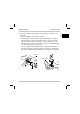
Basler IP Fixed Dome Cameras Installation Guide Installationsanleitung Third Language Fourth Langauge ra ft Fifth Language For BIP2-DXXXXc-dn Models ra ftD Sixth Language D Document Number: AW001014 Version: 04 Language: 000 Release Date: 27 March 2012 Seventh Language Eighth Langauge
Contacting Basler Support Worldwide Europe and the Middle East: Basler AG An der Strusbek 60 - 62 22926 Ahrensburg Germany Phone: +49-4102-463-303 Fax: +49-4102-463-599 Email: bc.support.ip.emea@baslerweb.com The Americas: Basler, Inc. 855 Springdale Drive Suite 203 Exton, PA 19341 U.S.A. Phone: +1-610-280-0171 Fax: +1-610-280-7608 Email: bc.support.ip.usa@baslerweb.com Asia: Basler Asia Pte. Ltd 8 Boon Lay Way # 03 - 03 Tradehub 21 Singapore 609964 Phone: +65-6425-0472 Fax: +65-6425-0473 Email: bc.
Installation Guide English Basler IP Fixed Dome Camera Installation Guide About This Document This document is intended to help you install your Basler IP Fixed Dome Cameras on a network. This document applies to Basler IP Fixed Dome Cameras that include the designation "BIP2" as part of the model name (see Section 9 on page 42 for list of the models covered by this document). When installation is complete, refer to the camera user’s manual for detailed information about operation and features.
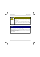
Installation Guide AW00101404000 CAUTION Electrical Shock Hazard Touching the camera’s internal components may result in an electrical shock. Do not attempt to access the electrical components in the camera base. The camera base contains no user serviceable parts. NOTICE Do not mount the dome camera in direct sunlight. 1. Direct sunlight can cause excessive heat buildup inside of the housing and may damage the camera. 2.
English Installation Guide The ambient temperature restricts and influences the behavior of some camera models under the following circumstances: Starting/Restarting the dome camera, e.g. after a power failure: BIP2-D1920c-dn (Outdoor) and BIP2-D1920c-dn (Outdoor,AF): If the ambient temperature is below 0 °C (32 °F), it can take several minutes until the processor starts. BIP2-D1920c-dn (Indoor) and BIP2-D1920c-dn (Indoor,AF): The ambient temperature must not be below 0 °C (32 °F).
Installation Guide AW00101404000 1 Hardware Overview RJ-45 Network/PoE RS-485 Terminal Block Main Terminal Block Fig. 1: Camera Hardware RJ-45 Network / PoE - Provides a 10/100 Ethernet connection and can be used to connect Power over Ethernet (IEEE 802.3af) to the camera. Main Terminal Block - Provides connections for an alternate camera power input (on outdoor dome camera models only), for the camera’s I/O ports, and for a DC output voltage.
Installation Guide Status Indicator LEDs Audio Connector Factory Default Button SD Card Slot Fig. 2: Camera Hardware Status Indicator LEDs - The green LED indicates the network connection speed. Off means the network speed is 10 MBits/s (or the network is not connected). On means the network speed is 100 MBits/s. The yellow LED indicates the level of network activity. Factory Default Button - Used to return the camera to factory default settings. See the dome camera user’s manual for details.
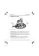
Installation Guide AW00101404000 2 Installation Procedure 2.1 Mounting the Camera Base Note: The camera base mounting procedure describes how to mount the camera directly to a solid surface such as a wall or a hard ceiling. Optional kits are available that allow the camera to be mounted in other fashions (such as in a suspended ceiling). If you are using one of these kits, refer to the instructions included with the kit to determine how to mount the camera. 1. Remove the dome from the camera base.
Installation Guide English 2. If you are installing an indoor dome camera, skip this step and go on to step 3 now. If you are installing an outdoor dome camera: Decide whether you will insert the network cable and the secondary cable through the cable pass-through hole in the side of the camera base or in the back of the camera base. (The secondary cable is the cable that can be used to carry alternate camera power, digital I/O, RS485, and audio signals to the camera.
Installation Guide AW00101404000 3. Tape the drilling template included with the camera to the wall or the ceiling in the location where the camera will be mounted, and mark the location of the mounting holes and the location of the cable pass-through hole. Notes: The anchors you use to mount the camera must be able to support at least two times the weight of the camera. Indoor dome camera models weigh 600 grams (1.3 poounds). Outdoor dome camera models weigh 1.0 kilogram (2.2 pounds).
Installation Guide English 6. Mount the camera base on the wall or ceiling by placing three screws through the mounting holes in the camera base and into the anchors as shown in the drawing on the next page. If you are installing an outdoor dome camera, be sure that each screw has an O-ring as shown in the drawing and be sure to place the weather-proof gasket between the camera base and the wall or ceiling as shown in the drawing.
Installation Guide AW00101404000 Screw (x3) Gasket (Not required for indoor dome cameras) O-ring (x3) (Not required for indoor dome cameras) 10 Basler IP Fixed Dome Cameras
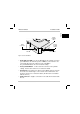
Installation Guide English 2.2 Installing Camera Cables Through the Side Pass-Through Hole Notes: This procedure describes how to install the cables using the weatherproof connection included with the outdoor dome camera kit. The procedure describes an installation that uses two cables, an Ethernet cable and a secondary cable. If you are only using a single PoE cable, installation is similar, but uses a grommet with only one groove. 1. Screw the nipple into the side of the camera base.
Installation Guide AW00101404000 2. Insert the cable(s) through the cap nut as shown below. Cap Nut Secondary Cable Ethernet Cable 3. Place the two cables in the grooves of the split grommet as shown below. Make sure that the ends of the cables extend 15 cm (6 inches) past the grommet as shown below. Note: If you are using only one cable, use the split grommet with only one groove.
4. For the connection to be weather proof, the cables must fit snugly in the grommet's grooves. Check now and make sure that the cables fit snugly in the grooves. If the cables are a loose fit: English Installation Guide a. Remove the grommet. b. Increase the diameter of the cables where they will pass through the grooves in the grommet by wrapping several layers of high quality plastic tape around each cable. c. Reapply the grommet to the cable and check the cables for a snug fit in the grooves. 5.
Installation Guide AW00101404000 7. Slide the cap nut up to the threaded end of the nipple and screw the cap nut onto the nipple as shown below. 8. Go on to Section 2.3.
Installation Guide English 2.3 Routing the Cables in the Housing and Making Connections Start with step 1 if you are using a network and a secondary cable. If you are only using a network cable, go to step 4. 1. Prepare the secondary cable: If you will only be making connections to the main terminal block, strip about 5 cm (2 inches) off of the cable’s outer sheath and loop the cable as shown below.
Installation Guide AW00101404000 2. If you are installing an outdoor dome camera and camera power will be supplied via the main terminal block: a. Make sure that your power supply meets the requirements for alternate camera power stated in Table 1 on page 36. b. Locate the two wires that will be used to supply power to the camera. c. Make sure that you can identify which wire is positive and which is ground. If you are not sure, use a voltmeter to identify the wires now. d.
3. Complete the wiring at the terminal blocks. a. If you will be using the camera’s I/O ports or the DC Out capabilities, refer to Table 1 on page 36 and to Figure 4 on page 40, and make the appropriate wiring connections at the main terminal block now. b.
Installation Guide AW00101404000 If you will not be using the camera’s audio connections, go on to Section 3 on page 20 now. If you will be using the camera’s audio connections, read the note below and then continue on with step 5. Note: The following steps describe using the Y-cable assembly that is included with the camera to make audio connections.
7. Route the Y-cable across the camera base as shown in the drawing below. 8. Plug a monaural microphone (or similar audio input device) with a 3.5 mm plug into the jack on the end of the cable labeled "Input". 9. The 3.5 mm monaural jack on the end of the cable labeled "Output" can be connected to an active speaker or, for example, to the line-in connector on a PC. Note that the output from this jack is not amplified and cannot drive headphones or a passive speaker. Note: Software switchable 2.
Installation Guide AW00101404000 3 Locating the Camera on Your Network and Making Initial Camera Access The location procedure assumes that your camera is on the same network subnet as your PC and that you have a Windows® operating system on your PC. The procedure uses a web browser to access your Basler IP Fixed Dome Camera. The recommended web browser is Microsoft Internet Explorer 8.0 or higher.
3. Double click on the BIP Finder shortcut. The BIP Finder software will open, will locate the Basler IP Camera(s) on your network, and will display them in a tree format. English Installation Guide The Basler IP Cameras connected to your network will be listed in the BIP Finder window by serial number. If you hover your cursor over a serial number, you will see a list of information for the camera, including the IP address, as shown below.
Installation Guide AW00101404000 4. Double click on a Basler IP Camera serial number in the BIP Finder window, your web browser will open and the browser will access the Basler Surveillance Web Client in the selected camera as shown below. Assuming that this is the first time you are accessing the camera via the web browser, you may see a message asking you to click on the Information Bar to allow installation of an ActiveX control.
Installation Guide English The Basler Surveillance Web Client will display a live stream from the camera as shown below. For complete information about using the Basler Surveillance Web Client to change the camera’s settings and view images from the camera, see the camera user’s manual. You can find the camera user’s manual on the CD delivered with your camera, or you can find the latest version of the manual in the Downloads section of the Basler website: www.basler-ipcam.
Installation Guide AW00101404000 4 Adjust the Aim, Zoom, and Focus NOTICE Using incorrect procedures when aiming the camera head can severely damage the camera. 1. DO NOT attempt to aim the camera head by pulling or pushing directly on the lens. 2. DO NOT over-pan or over-rotate the camera head. Panning or rotating the camera head too far can damage the cable between the camera base and the camera head.
can pan or rotate the head is limited by the stress on the cable between the camera base and the camera head. c. When you are panning or rotating the camera head, observe the cable and stop the panning or rotation when the cable begins to look like it will become over-stressed. Pan Rotation Carriage Camera Head Rotate Tilt Panning Plate Cable Note: When adjusting the zoom and focus, keep in mind that the field of view will become slightly smaller when you put the dome in place. To adjust the zoom: 1.
Installation Guide AW00101404000 To adjust the focus: Depending on whether you are using a dome camera model with or without autofocus functionality, there are two different ways to adjust the focus: manual focus adjustment and autofocus adjustment. For more information about the specific camera models with autofocus functionality, refer to the basic specification tables in Section 9 on page 42.
Autofocus adjustment When you are using a camera model with autofocus functionality, the focus is adjusted automatically through a motorized lens as shown in the drawing on the next page. NOTICE DO NOT attempt to move the lens manually. This might severely damage the stepper motor used for autofocusing. Installation of autofocus dome cameras has to be done within a limited temperature range since the autofocus functionality does not operate at extremely low temperatures.
Installation Guide AW00101404000 Zoom Puller Lens is moved automatically 1. In the Basler Surveillance Web Client, click on the One Push Focus button on the left side of the Basler tool bar. The autofocus sequence starts. The focused image is shown on the Live Stream tab, where a blue/grey bar indicates the focusing process as long as the focus is adjusted.
Installation Guide English 2. Check the focused image on the Live Stream tab. If necessary, you can readjust the focus stepwise: 3. For this purpose, open the Focus tab in the Image Controls group, if it has not already been opened. 4. Use the Focus Move buttons to move the lens in fine (>), medium (>>), or coarse (>>>) steps to readjust the focus towards near (N) or far (F). The One Push Focus command is used to focus on the object/s of interest only once. (No automatic refocusing during operation.
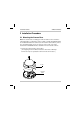
Installation Guide AW00101404000 5 Complete the Installation 1. Install the desiccant pack (outdoor dome cameras only): a. Get the desiccant pack, cable tie, and stick-on cable tie anchor from the installation kit (the desiccant pack will be in a foil wrapper). Cable Tie Desiccant Pack (in foil wrapper) Stick-on Cable Tie Anchor b. Place the stick-on anchor on the camera base as shown below.
2. If you will be using an SD card, insert the card (either a micro SD or micro SDHC card) into the SD card slot now. 3. Clean the dome with a soft cloth to remove any dust or fingerprints. 4. Use the screw included with the installation kit to attach the safety strap from the dome to the camera base as shown below. Note: On dome cameras with a plastic housing, the screw should be tightened to a maximum of 25 cNm (35.4 in-oz). Overtightening the screw can result in non-repairable damage to the housing.
Installation Guide AW00101404000 5. Use the three captive tamper-proof screws in the dome and the special torx wrench included with the installation kit to mount the dome to the camera base as shown below. Before the three screws are completely tightened, rotate the plastic dome so that the clear area in the black coating on the dome is properly aligned with the lens. Once the screws are completely tightened, the plastic dome will be locked in place. Captive Tamper-proof Screw (x3) 6.
6 Firmware Updates To ensure that your camera’s functionality is up to date, you should periodically check the Downloads section of the Basler website to see if a firmware update file is available. The website address is: www.basler-ipcam.com You can use the Basler Surveillance Web Client to view the current firmware version on a camera and to perform a firmware update. For more information about using the client to view the current firmware version or to update firmware, see the camera user’s manual.
Installation Guide AW00101404000 7 The Main Terminal Block The terminal block on the front of the camera base can be used to: provide alternate power to the camera when PoE is not used (this functionality is available on outdoor dome cameras only) access the camera’s I/O ports power a small DC device such as a relay limit the camera’s power consumption by disabling the camera’s heater NOTICE Do not apply AC voltages or voltages out of specification to the main terminal block. 1.
Installation Guide Present on outdoor dome cameras only English The assignments for the wire fixing holes in the main terminal block are as shown below and explained in Table 1 on page 36. Release Tabs Wire Fixing Holes Fig. 3: Main Terminal Block The main terminal block is a push-in type of connector. Either solid or stranded wires can be inserted into the wire fixing holes in the terminal block.
Installation Guide AW00101404000 The functionality of each wire fixing hole in the main terminal block is as described in Table 1. Hole Name: Gnd (outdoor dome cameras only) Function: Ground for alternate camera power. Note: The ground for alternate camera power, the I/O ground, and the RS-485 ground are all isolated from each other. Hole Name: VDC (outdoor dome cameras only) Function: Use this fixing hole to supply alternate power to the camera (i.e.
Hole Name: I/O-0, I/O-1 Function: I/O port 0 and I/O port 1 respectively. Each I/O port can be set to operate either as an input or as an output. The choice of whether a particular I/O port will operate as an input or an output and how it will function is made by setting camera parameters (see the camera user’s manual for details about setting camera parameters). For an I/O port set as an input: In the schematic drawing on page 40, I/O-0 has been set to operate as an input.
Installation Guide AW00101404000 (I/O-0, I/O-1 description continued from the previous page.) For an I/O port set as an output: In the schematic drawing on page 40, I/O-1 has been set to operate as output. An output port employs an open collector transistor connected to ground as shown in the schematic. As indicated in the table below, an output port will or will not be connected to ground via the transistor depending on the state of the port and whether the port is or is not set to invert.
Hole Name: DC Out Function: DC Out supplies unregulated +5.6 VDC and can be used to power a small device such as a relay. For example, the relay shown in the schematic drawing on page 40 could be connected to DC Out rather than to an external source of power. The maximum allowed load on DC Out is 50 mA. If an inductive load such as a relay is used with DC Out, a diode must be connected in parallel with the load as shown in the schematic page 40.
Installation Guide AW00101404000 Camera +24 VDC Max Isolated I/O Circuit DC Out +5 VDC 1 kΩ I/O-1 (Set as an output) Relay +5 VDC 1 kΩ I/O-0 Switch (Set as an input) I/O Gnd (isolated) Isolated Alternate Camera Power Circuit (Outdoor dome cameras only) Heater Off (Jumper Heater Off to Gnd to disable heater) +12 to +24 VDC VDC Camera Power Gnd (isolated) Isolated RS-485 Circuit B- RS-485 B- A+ RS-485 A+ RS-485 Gnd RS-485 Gnd (isolated) Device Fig.
8 The RS-485 Terminal Block The 3-hole terminal block on the right side of the camera base can be used to make an RS-485 connection to the camera. The assignments for the wire fixing holes in the terminal block are as shown below. The A+, B-, and Gnd connections are standard for an RS-485 connection. The RS-485 ground is isolated from the camera’s power ground and I/O ground. Release Tabs Wire Fixing Holes Fig. 5: RS-485 Terminal Block The terminal block is a push-in type of connector.
Installation Guide AW00101404000 9 Basic Specifications Specification BIP2-D1000c-dn BIP2-D1300c-dn Sensor Progressive scan CCD Progressive scan CCD Effective Pixels 1024 (H) x 768 (V) 1280 (H) x 960 (V) Frame Rate Full resolution: MJPEG 30 fps Operating Conditions Ambient temperature: -40 °C to 50 °C (-40 °F to 122 °F) Ambient humidity: < 90% relative humidity (non-condesing) Specification BIP2-D1920c-dn (Outdoor) / BIP2-D1920c-dn (Indoor) / BIP2-D1920c-dn (Outdoor,AF) BIP2-D1920c-dn (Indoo
Installationsanleitung Sprache Sprache Sprache Nach abgeschlossener Installation finden Sie detaillierte Informationen über Betrieb und Funktionen im Benutzerhandbuch der Kamera. Das Benutzerhandbuch befindet sich auf der mit der Kamera gelieferten CD, die aktuellste Version und andere Sprachversionen können im Downloadbereich unserer Website: www.basler-ipcam.com heruntergeladen werden. Sprache Dieses Dokument soll bei der Installation der Basler IP Fixed-Dome-Kameras in einem Netzwerk helfen.
Installationsanleitung AW00101404000 Sicherheitshinweise WARNUNG Notwendigkeit der fachgerechten Montage Die Montage der Kamera sollte unter Beachtung aller geltenden Bestimmungen von qualifiziertem ServicePersonal vorgenommen werden. Die Verbindung zwischen Wand bzw. Decke und Kamera muss für mindestens das doppelte Kameragewicht ausgelegt sein. Das Gewicht der Kamera mit dem Modellnamen "BIP2D1920c-dn (Indoor)" beträgt 600 Gramm. Das Gewicht aller anderen Kameramodelle beträgt 1,0 Kilogramm.
HINWEIS Bei der Wahl der Montageposition der Dome-Kamera direktes Sonnenlicht vermeiden. 1. Direkte Sonneneinstrahlung führt zu übermäßiger Wärmeentwicklung im Kameragehäuse, dadurch können Schäden an der Kamera verursacht werden. Sprache Sprache Sprache Sprache Sprache 2. Die beste Bildqualität wird erreicht, wenn die Kamera nicht im direkten Sonnenlicht platziert wird.
Installationsanleitung AW00101404000 Unter den folgenden Umständen wird bei einigen Kameramodellen das Verhalten durch die Umgebungstemperatur eingeschränkt und beeinflusst: Starten/Neustarten der Dome-Kamera, z.B. nach Unterbrechung der Stromversorgung: BIP2-D1920c-dn (Outdoor) und BIP2-D1920c-dn (Outdoor,AF): Ist die Umgebungstemperatur unter 0 °C (32 °F), kann es einige Minuten dauern, bis der Prozessor startet.
AW00101404000 Installationsanleitung Sprache RS-485Klemmleiste Abb. 1: Hardware RJ-45 Netzwerk/PoE - 10/100 Ethernet-Anschluss, auch für Stromversorgung der Kamera über Power over Ethernet (IEEE 802.3af). Hauptklemmleiste - Anschlüsse für eine alternative Stromversorgung der Kamera (nur gültig für Dome-Kameramodelle für den Außenbereich), für Ein- und Ausgangsschnittstellen und für einen Gleichspannungsausgang. (Weitere Informationen, siehe Abschnitt 7 auf Seite 79.
Installationsanleitung AW00101404000 LED-Statusanzeige Factory DefaultKnopf AudioAnschluss SD-Kartensteckplatz Abb. 2: Hardware LED-Statusanzeige - die grüne LED zeigt die Geschwindigkeit der Netzwerkverbindung an. Leuchtet die LED nicht, beträgt die Geschwindigkeit der Netzwerkverbindung 10 Mbit/s (oder die Netzwerkverbindung ist unterbrochen). Leuchtet die LED, beträgt die Geschwindigkeit der Netzwerkverbindung 100 Mbit/s. Die gelbe LED zeigt die Netzwerkaktivität an.
AW00101404000 Installationsanleitung English 2 Installationsablauf Sprache Sprache Sprache 1. Kuppelgehäuse vom Kamerasockel entfernen. (Kuppelgehäuse ist zum Transport mit Klebeband am Kamerasockel befestigt. Klebeband entfernen, um Kuppelgehäuse vom Kamerasockel abnehmen zu können.) Sprache Hinweis: In diesem Montageablauf wird die Anbringung des Kamerasockels auf einer festen Oberfläche (Massivdecke oder Wand) beschrieben.
Installationsanleitung AW00101404000 2. Bei Installation einer Dome-Kamera für den Innenbereich den folgenden Schritt überspringen und mit Schritt 3 fortfahren. Bei Installation einer Dome-Kamera für den Außenbereich: Netzwerkkabel und zweites Kabel können wahlweise durch die Kabeleinführung in der Seite oder auf der Rückseite des Kamerasockels eingeführt werden.
Sprache 4. Die drei angezeichneten Bohrlöcher in Wand oder Decke bohren. Der Durchmesser der Bohrlöcher sollte der verwendeten Befestigungsausführung entsprechen. Deutsch Wenn bei der Montage die drei Schrauben, die den Kamerakörper mit dem Sockel verbinden, gelöst werden und der Kamerakörper vom Sockel getrennt wird, um einen besseren Zugang zu den Befestigungslöchern zu erhalten, auf Folgendes achten: Beim erneuten Verschrauben des Kamerakörpers mit dem Sockel die drei Schrauben nicht überdrehen.
Installationsanleitung AW00101404000 6. Kamerasockel an Wand oder Decke befestigen. Dazu die drei Schrauben von innen durch die Befestigungslöcher im Kamerasockel in die in der Wand bzw. Decke eingesetzten Dübel einschrauben, siehe Abbildung auf der folgenden Seite. Bei Installation einer Dome-Kamera für den Außenbereich sicherstellen, dass sich auf jeder Schraube ein Dichtungsring befindet und dass gemäß der Abbildung die witterungsbeständige Flachdichtung zwischen Wand bzw.
Installationsanleitung Sprache Deutsch English AW00101404000 Sprache Sprache Schraube (x3) Sprache Sprache Flachdichtung (nicht erforderlich für Dome-Kameras für den Innenbereich) Sprache Dichtungsring (x3) (nicht erforderlich für Dome-Kameras für den Innenbereich) Basler IP Fixed-Dome-Kameras 53
Installationsanleitung AW00101404000 2.2 Installation der Kamerakabel durch seitliche Kabeleinführung Hinweis: Dieser Ablauf beschreibt die Installation der Kabel mit der im Lieferumfang der Dome-Kamera für den Außenbereich enthaltenen witterungsbeständigen Kabelverschraubung. Der Ablauf bezieht sich auf die Installation von zwei Kabeln, das Ethernetkabel und das zweite Kabel (für die alternative Stromversorgung bei Nichtverwendung von PoE).
Installationsanleitung Deutsch Zweites Kabel Ethernet-Kabel 3. Kabel, wie unten abgebildet, in jeweils eine Kabelführung des geteilten Dichteinsatzes einlegen. Sicherstellen, dass die Kabelenden mindestens 15 cm über den Dichteinsatz überstehen. 15 c Sprache Hinweis: Bei Verwendung nur eines Kabels den geteilten Dichteinsatz mit einzelner Kabelführung verwenden. Sprache Überwurfmutter English 2. Kabel wie unten abgebildet durch die Überwurfmutter führen.
Installationsanleitung AW00101404000 4. Um sicherzustellen, dass die Verbindung witterungsbeständig ist, müssen die Leitungen fest in den Kabelführungen des Dichteinsatzes anliegen. Überprüfen und sicherstellen, dass die Kabel fest in den Kabelführungen anliegen. Wenn die Kabel nicht fest anliegen: a. Dichteinsatz abnehmen. b.
AW00101404000 Installationsanleitung English 7. Überwurfmutter wie in der Abbildung unten gezeigt bis zur Kabelverschraubung schieben und festschrauben. Deutsch 8. Fortfahren mit Abschnitt 2.3.
Installationsanleitung AW00101404000 2.3 Kabelführung im Gehäuse und Herstellen der Verbindungen Mit Schritt 1 beginnen, wenn ein Netzwerkkabel und ein zweites Kabel verwendet werden. Wenn nur ein Netzwerkkabel angeschlossen werden soll, siehe ab Schritt 4. 1. Das zweite Kabel vorbereiten: Wenn nur an der Hauptklemmleiste Leitungen angeschlossen werden, circa 5 cm der Ummantelung entfernen und das Kabel wie unten gezeigt im Gehäuse in eine Schleife legen.
Deutsch Sprache Sprache Positive Leitung einführen Sprache Masseleitung einführen Sprache a. Sicherstellen, dass die Stromversorgung den in Tabelle 1 auf Seite 81 genannten Anforderungen an die alternative Stromversorgung entspricht. b. Die beiden Leitungen für die Stromversorgung der Kamera ermitteln. c. Sicherstellen, dass die positive Leitung und die Masseleitung richtig bestimmt sind. Bestehen Unsicherheiten, Leitungen mit einem Spannungsmessgerät ausmessen. d.
Installationsanleitung AW00101404000 3. Verdrahtung an den Klemmleisten vervollständigen. a. Wenn die I/O-Schnittstellen oder die Gleichspannungsversorgung genutzt werden, siehe Tabelle 1 auf Seite 81 und Abbildung 4 auf Seite 85, sind die entsprechenden Verdrahtungen dafür jetzt an der Hauptklemmleiste vorzunehmen. b.
Installationsanleitung Sprache Deutsch 4. Verbindung zwischen Netzwerkkabel und RJ-45-Anschluss herstellen. Das Kabel ist am einfachsten anzuschließen, wenn wie in der Abbildung unten gezeigt eine Schleife gebildet wird. English AW00101404000 Sprache RJ-45-Steckverbindung Wenn die Audio-Anschlüsse der Kamera verwendet werden, Hinweis unterhalb lesen und mit Schritt 5 fortfahren.
Installationsanleitung AW00101404000 5. Y-Kabel-Baugruppe dem Kamerazubehör entnehmen. 6. Vierpoligen Stecker am Ende des Kabels, wie unterhalb gezeigt, in den Audio-Anschluss des Kamerasockels stecken. 7. Y-Kabel im Kamerasockel verlegen, wie in der folgenden Abbildung gezeigt.
Installationsanleitung Hinweis: Am Eingang stehen über die Software schaltbare 2,2 V zur Verfügung. Üblicherweise wird diese Möglichkeit von Mikrofonen genutzt, die eine Stromversorgung benötigen. Am Eingang sind weiterhin über die Software schaltbare 20 dB Verstärkung verfügbar. Weitere Informationen, siehe Benutzerhandbuch der Kamera. Basler IP Fixed-Dome-Kameras 63 Sprache Sprache 9.
Installationsanleitung AW00101404000 3 Lokalisieren der Kamera im Netzwerk und erster Zugriff auf die Kamera Bei der Suche der Kamera im Netzwerk wird vorausgesetzt, dass sich die Kamera im selben Subnetz wie der Rechner befindet und dass Windows® als Betriebssystem des Rechners verwendet wird. Es wird ein Webbrowser verwendet, um auf die Basler IP Fixed-DomeKamera zuzugreifen. Der empfohlene Webbrowser ist Microsoft Internet Explorer 8.0 oder höher.
Basler IP Fixed-Dome-Kameras 65 Sprache Hinweis: Die BIP Finder-Software hat ein breites Spektrum an Funktionen, einschließlich der Möglichkeit, umfangreiche Informationen zu jeder im Netzwerk befindlichen Kamera anzuzeigen und Firmware-Updates auf diesen Kameras durchzuführen. Um sich mit allen Möglichkeiten der Software vertraut zu machen, empfehlen wir die Durchsicht der im BIP Finder-Softwarepaket enthaltenen Hilfedatei.
Installationsanleitung AW00101404000 4. Auf die Seriennummer der Kamera im Fenster des BIP Finders doppelklicken. Der unten abgebildete Screenshot zeigt, wie sich der Webbrowser öffnet und auf den Basler Surveillance Web Client in der ausgewählten Kamera zugreift. Beim ersten Zugriff auf die Kamera über den Webbrowser kann eine Meldung erscheinen, die die Installation eines ActiveX-Steuerelements durch Klicken auf die Informationsleiste empfiehlt.
Installationsanleitung Basler IP Fixed-Dome-Kameras 67 Sprache Umfassende Informationen zur Nutzung des Basler Surveillance Web Client für die Änderung von Kameraeinstellungen und Ansicht von Kamerabildern, siehe Benutzerhandbuch. Das Benutzerhandbuch befindet sich auf der mit der Kamera gelieferten CD, die aktuellste Version kann im Downloadbereich unserer Website www.basler-ipcam.com heruntergeladen werden.
Installationsanleitung AW00101404000 4 Einstellen von Sichtbereich, Zoom und Bildschärfe HINWEIS Eine unsachgemäße Vorgehensweise beim Ausrichten des Kamerakopfes kann zu schwerwiegenden Schäden an der Kamera führen. 1. NIEMALS versuchen, durch Ziehen oder Schieben direkt am Objektiv den Kamerakopf auszurichten. 2. NIEMALS den Kamerakopf zu weit schwenken oder drehen. Wird der Kamerakopf zu weit geschwenkt oder gedreht, kann das Kabel zwischen Kamerasockel und Kamerakopf beschädigt werden.
Sprache b. Um den Kamerakopf zu schwenken oder zu drehen, die Seiten des Drehbügels greifen. Durch das Greifen der Seiten des Drehbügels kann entweder der Schwenkteller oder der Drehbügel gedreht werden. Der Umfang, in dem der Kamerakopf geschwenkt oder gedreht werden kann, ist durch die Dehnung des Kabels zwischen Kamerasockel und Kamerakopf begrenzt. c. Beim Schwenken und Drehen des Kamerakopfes auf das Kabel achten und die Bewegungen stoppen, bevor das Kabel überdehnt wird.
Installationsanleitung AW00101404000 Hinweis: Bei der Einstellung von Zoom und Bildschärfe berücksichtigen, dass der Bildwinkel geringfügig kleiner wird, sobald das Kuppelgehäuse aufgesetzt ist. Einstellen des Zooms: 1. Zoomregler durch Drehen nach links lösen, wie in der Zeichnung auf der nächsten Seite gezeigt. 2. Regler nach links und rechts bewegen und so den Zoomfaktor einstellen. 3. Ist der Zoomfaktor eingestellt, Zoomregler festziehen.
Installationsanleitung English AW00101404000 Schärferegler Einstellen der Bildschärfe mit Autofokus-Funktion Sprache Wird ein Kameramodell mit Autofokus-Funktion verwendet, erfolgt das Einstellen der Bildschärfe automatisch durch ein motorisiertes Objektiv, wie in der Zeichnung auf der nächsten Seite zu sehen ist. HINWEIS Sprache NIEMALS versuchen das Objektiv manuell zu bewegen. Dies kann zu schwerwiegenden Schäden an dem für die Autofokus-Funktion verwendeten Schrittmotor führen.
Installationsanleitung AW00101404000 Die Installation der Dome-Kameras mit AutofokusFunktion muss in einem begrenzten Temperaturbereich erfolgen, da die Autofokus-Funktion bei extrem niedrigen Temperaturen nicht arbeitet.
Installationsanleitung English AW00101404000 2. Fokussiertes Bild in der Registerkarte Live Stream prüfen. Falls erforderlich kann die Bildschärfe schrittweise nachgestellt werden: 3. Dazu Registerkarte Focus in der Gruppe Image Controls öffnen. Sprache Sprache 4. Schaltflächen Focus Move verwenden, um mit dem Objektiv in feinen (>), mittleren (>>) oder groben (>>>) Schritten die Bildschärfe für nah (N) oder fern (F) nachzustellen. Sprache Sprache Die Autofokus-Sequenz startet.
Installationsanleitung AW00101404000 Das Kommando One Push Focus wird zum einmaligen Einstellen der Bildschärfe auf gewünschte Objekte verwendet. (Die Bildschärfe wird während des Betriebes nicht erneut nachgestellt.
AW00101404000 Installationsanleitung English 5 Installation abschließen Deutsch 1. Trockenmittelbeutel anbringen (gilt nur für Dome-Kameras für den Außenbereich): Trockenmittelbeutel (in Schutzfolie) b. Klebesockel für Kabelbinder am Kamerasockel anbringen, wie in der folgenden Abbildung gezeigt. Trockenmittelbeutel aus der Schutzfolie entnehmen und mit dem Kabelbinder am Klebesockel befestigen. Das Ende des Kabelbinders abschneiden.
Installationsanleitung AW00101404000 2. Wenn eine SD-Karte (Speicherkartenformat entweder microSD oder microSDHC) verwendet wird, diese jetzt in den SD-Kartensteckplatz einstecken. 3. Kuppelgehäuse mit einem weichen Tuch abwischen, um Staub und Fingerabdrücke zu entfernen. 4. Beiliegende Schraube verwenden, um das Sicherheitsband des Kuppelgehäuses am Kamerasockel zu befestigen.
5. Die drei verliersicheren, manipulationssicheren Schrauben im Kuppelgehäuse und den beiliegenden Torxschlüssel verwenden, um das Kuppelgehäuse mit dem Kamerasockel zu verbinden, siehe unten. Sprache Sprache Bevor die drei Schrauben fest angezogen werden, Kunststoffkuppel so drehen, dass der durchsichtige Bereich im schwarz getönten Kuppelgehäuse mit dem Objektiv gleichgerichtet ist. Sind die Schrauben fest angezogen, ist die Kunststoffkuppel im Kuppelgehäuse eingerastet.
Installationsanleitung AW00101404000 6 Firmware-Updates Um sicherzustellen, dass die Funktionalität der Kamera auf dem neuesten Stand ist, sollten Sie sich regelmäßig im Downloadbereich der Basler-Website informieren, ob es neue Dateien zum Update der Firmware gibt. Die Internetadresse lautet: www.basler-ipcam.com Mithilfe des Basler Surveillance Web Clients können Sie sich die aktuell installierte Firmware-Version auf der Kamera anzeigen lassen und ein Firmware-Update durchführen.
Installationsanleitung English 7 Die Hauptklemmleiste Stromversorgung für ein kleines Gleichspannungsgerät (z.B. ein Relais) Begrenzung der Kamera-Leistungsaufnahme durch Abschaltung der Heizung Sprache Zugriff auf I/O-Schnittstellen der Kamera Sprache Sprache HINWEIS Keine Wechselspannung oder von der Spezifikation abweichende Spannung an die Hauptklemmleiste anlegen. 1. Nur Gleichspannung anlegen. Das Anlegen von Wechselspannung kann zu schwerwiegenden Schäden an der Kamera führen. 2.
Installationsanleitung AW00101404000 Die Anschlussbelegung der Befestigungsklemmen der Hauptklemmleiste ist unten angegeben und in Tabelle 1 auf Seite 81 erläutert. Nur bei Dome-Kameras für den Außenbereich vorhanden Entriegelung Befestigungsklemmen Abb. 3: Hauptklemmleiste Die Hauptklemmleiste ist als Einsteckverbinder ausgeführt. An den Befestigungsklemmen der Klemmleiste können entweder Massivdrahtleitungen oder Litzenleitungen angeschlossen werden.
AW00101404000 Installationsanleitung English Die Funktionsweise der einzelnen Befestigungsklemmen der Hauptklemmleiste ist in Tabelle 1 beschrieben. Funktion: Diese Befestigungsklemme zur alternativen Stromversorgung der Kamera verwenden (falls die Stromversorgung der Kamera nicht über PoE realisiert wird). Nennbetriebsbereich: +12 bis +24 V Gleichspannung Max.
Installationsanleitung AW00101404000 Befestigungsklemme: I/O-0, I/O-1 Funktion: entsprechend Schnittstelle I/O-0 und I/O-1. Jede I/O-Schnittstelle kann eingestellt werden, um als Ein- oder Ausgang zu arbeiten. Die Funktionswahl und ob eine bestimmte I/O-Schnittstelle als Eingang oder Ausgang arbeitet, werden bei der Einstellung der Kameraparameter vorgenommen. (Weitere Informationen zur Einstellung der Kameraparameter, siehe Benutzerhandbuch.
Für eine I/O-Schnittstelle, die als Ausgang geschaltet ist: Im Schaltschema auf Seite 85 wurde I/O-1 eingestellt, um als Ausgang zu arbeiten. Eine Ausgangsschnittstelle verfügt über einen Transistor mit offenem Kollektor, der, wie im Schaltschema gezeigt, mit Masse verbunden ist. In Abhängigkeit vom Zustand und vom Modus des Ausgangs (normal oder invertiert), wird dieser über den Transistor mit Masse verbunden oder nicht verbunden, siehe Tabelle unten.
Installationsanleitung AW00101404000 Befestigungsklemme: DC Out Funktion: Der Ausgang DC Out liefert unreguliert +5,6 V Gleichspannung und kann ein kleines Gerät wie ein Relais mit Energie versorgen. Beispielsweise könnte das auf Seite 85 abgebildete Relais statt an eine externe Stromversorgung an DC Out angeschlossen werden. Die maximale Last am Ausgang DC Out ist 50 mA. Wenn eine induktive Last, z. B.
Installationsanleitung Kamera Ein-/Ausgangskreis isoliert English AW00101404000 max. +24 VDC DC Out Deutsch +5 VDC 1 kΩ I/O-1 (als Ausgang geschaltet) Sprache Relais +5 VDC 1 kΩ Schalter Sprache I/O-0 (als Eingang geschaltet) Heater Off (Brücke Heater Off zu Gnd, Heizung ausschalten) +12 bis +24 VDC Sprache VDC Isolierter RS-485Schaltkreis B- RS-485 B- A+ RS-485 A+ Sprache Masse Stromversorgung Kamera (isoliert) RS-485 Gnd Masse RS-485 (isoliert) Gerät Abb.
Installationsanleitung AW00101404000 8 Die RS-485-Klemmleiste Die Klemmleiste mit 3 Befestigungsklemmen an der rechten Seite des Kamerasockels kann verwendet werden, um eine RS-485-Verbindung zur Kamera herzustellen. Die Abbildung unten zeigt die Anschlussbelegung für die Befestigungsklemmen der Klemmleiste. Die Anschlüsse A+, B- und Gnd sind bei einer RS-485-Schnittstelle standardmäßig vorhanden.
AW00101404000 Installationsanleitung Progressive Scan CCD 1024 (H) x 768 (V) 1280 (H) x 960 (V) Bildrate volle Auflösung: MJPEG 30 fps Betriebsbedingungen Umgebungstemperatur: -40 °C bis 50 °C (-40 °F bis 122 °F) Luftfeuchtigkeit der Umgebung: < 90 % relative Luftfeuchtigkeit (nicht kondensierend) Spezifikation BIP2-D1920c-dn (Outdoor) / BIP2-D1920c-dn (Indoor) / BIP2-D1920c-dn (Outdoor,AF) BIP2-D1920c-dn (Indoor,AF) Sensor Progressive Scan CMOS Progressive Scan CMOS Effektive Pixel 1920 (H)