
User`s manual


Physical Interface
36 Basler ace Camera Link
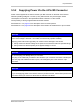
Figure 10 shows an example of a typical circuit you can use to input a signal into the camera.
For more information about GPIO pin assignments and pin numbering, see Section 5.2 on page 24.
For more information about setting the GPIO line operation, see Section 6.1 on page 47.
Your
Gnd
Your
Gnd
Input
Voltage
+24 VDC
Absolute
Max.
1
2
3
4
4-Pin
Receptacle
180
Ω
1k
Gnd
GPIO_In
U
GPIO_Gnd
GPIO_In_Ctrl
TLP281
Camera
Gnd
100 nF
Q
BF545C
D
BAS
16XV2T1
3.3 V
49.9
Ω
(to FPGA)
GPIO_Gnd
Fig. 10: Typical Input Circuit