
User`s manual


Physical Interface
30 Basler aviator Camera Link
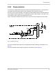
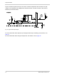
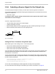
Figure 12 shows a typical circuit you can use to monitor the output line with an LED or an opto-
coupler. In this example, the voltage for the external circuit is +24 VDC. Current in the circuit is
limited by an external resistor.
Fig. 12: Typical LED Output Signal
For more information about output line pin assignments and pin numbering, see Section 2.2 on
page 16.
For more information about using the output lines, see Section 2.9.4 on page 32.